HP rp3440 User Service Guide, Sixth Edition - HP 9000 rp3410/rp3440 - Page 154
Inserting the DIMM Into the Connector Socket, Removing and Replacing the Memory Airflow
 |
View all HP rp3440 manuals
Add to My Manuals
Save this manual to your list of manuals |
Page 154 highlights
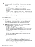
Figure 6-34 Inserting the DIMM Into the Connector Socket 6. Replace the memory airflow guide. (See "Removing and Replacing the Memory Airflow Guide" (page 144).) 7. Replace the top cover. 8. Reconnect the power and external cables and turn on the server. 9. Verify the memory replacement and operation by using the system utilities. (For additional information, see Appendix B (page 199) or the HP Integrity and HP 9000 iLO MP Operations Guide.) • Use the iLO MP commands to verify operation. • Use the BCH commands to verify operation. • Use diagnostics provided by the ODE to exercise the newly installed memory. 154 Removing and Replacing Components
-
 1
1 -
2
-
3
-
4
-
5
-
6
-
7
-
8
-
9
-
10
-
11
-
12
-
13
-
14
-
15
-
16
-
17
-
18
-
19
-
20
-
21
-
22
-
23
-
24
-
25
-
26
-
27
-
28
-
29
-
30
-
31
-
32
-
33
-
34
-
35
-
36
-
37
-
38
-
39
-
40
-
41
-
42
-
43
-
44
-
45
-
46
-
47
-
48
-
49
-
50
-
51
-
52
-
53
-
54
-
55
-
56
-
57
-
58
-
59
-
60
-
61
-
62
-
63
-
64
-
65
-
66
-
67
-
68
-
69
-
70
-
71
-
72
-
73
-
74
-
75
-
76
-
77
-
78
-
79
-
80
-
81
-
82
-
83
-
84
-
85
-
86
-
87
-
88
-
89
-
90
-
91
-
92
-
93
-
94
-
95
-
96
-
97
-
98
-
99
-
100
-
101
-
102
-
103
-
104
-
105
-
106
-
107
-
108
-
109
-
110
-
111
-
112
-
113
-
114
-
115
-
116
-
117
-
118
-
119
-
120
-
121
-
122
-
123
-
124
-
125
-
126
-
127
-
128
-
129
-
130
-
131
-
132
-
133
-
134
-
135
-
136
-
137
-
138
-
139
-
140
-
141
-
142
-
143
-
144
-
145
-
146
-
147
-
148
-
 149
149 -
 150
150 -
 151
151 -
 152
152 -
 153
153 -
 154
154 -
 155
155 -
 156
156 -
 157
157 -
 158
158 -
 159
159 -
160
-
161
-
162
-
163
-
164
-
165
-
166
-
167
-
168
-
169
-
170
-
171
-
172
-
173
-
174
-
175
-
176
-
177
-
178
-
179
-
180
-
181
-
182
-
183
-
184
-
185
-
186
-
187
-
188
-
189
-
190
-
191
-
192
-
193
-
194
-
195
-
196
-
197
-
198
-
199
-
200
-
201
-
202
-
203
-
204
-
205
-
206
-
207
-
208
-
209
-
210
 |
 |
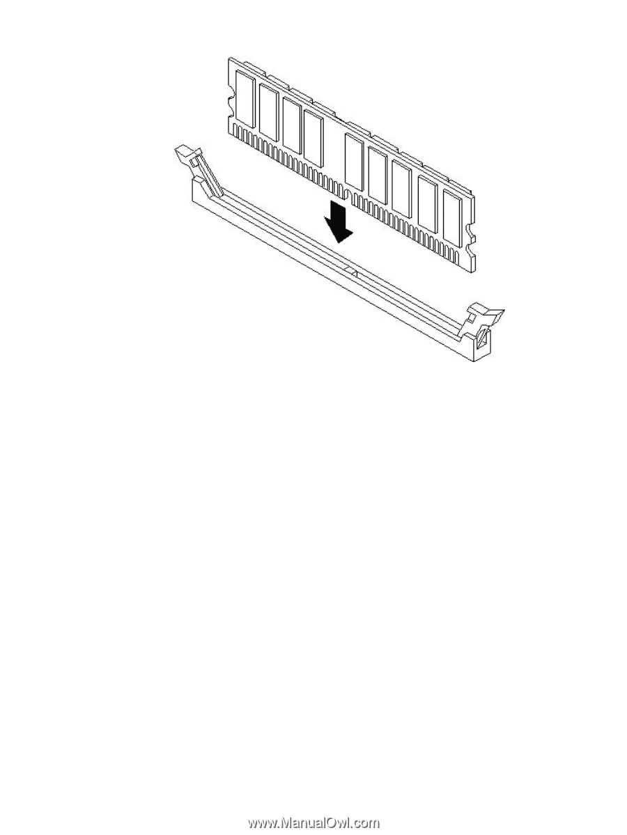
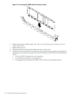
Figure 6-34 Inserting the DIMM Into the Connector Socket
6.
Replace the memory airflow guide. (See
“Removing and Replacing the Memory Airflow
Guide” (page 144)
.)
7.
Replace the top cover.
8.
Reconnect the power and external cables and turn on the server.
9.
Verify the memory replacement and operation by using the system utilities. (For additional
information, see
Appendix B (page 199)
or the
HP Integrity and HP 9000 iLO MP Operations
Guide
.)
•
Use the iLO MP commands to verify operation.
•
Use the BCH commands to verify operation.
•
Use diagnostics provided by the ODE to exercise the newly installed memory.
154
Removing and Replacing Components