HP rp3440 User Service Guide, Sixth Edition - HP 9000 rp3410/rp3440 - Page 188
Replacing the Power Supply Interface Module, Replacing the System Board
 |
View all HP rp3440 manuals
Add to My Manuals
Save this manual to your list of manuals |
Page 188 highlights
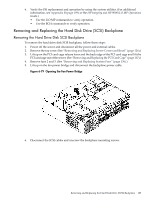
1. Place the PSI module into the chassis by sliding the module retaining tab into the socket on the hard disk drive bay wall. Figure 6-77 Replacing the Power Supply Interface Module 2. Screw in the PSI module mounting screw and secure the power cables behind the holding clips. Figure 6-78 Securing the Power Supply Interface Module and Cables 3. Replace the system board. (See "Replacing the System Board" (page 180).) 4. Replace the top cover. 5. Reconnect all the power and external cables. 188 Removing and Replacing Components
-
 1
1 -
2
-
3
-
4
-
5
-
6
-
7
-
8
-
9
-
10
-
11
-
12
-
13
-
14
-
15
-
16
-
17
-
18
-
19
-
20
-
21
-
22
-
23
-
24
-
25
-
26
-
27
-
28
-
29
-
30
-
31
-
32
-
33
-
34
-
35
-
36
-
37
-
38
-
39
-
40
-
41
-
42
-
43
-
44
-
45
-
46
-
47
-
48
-
49
-
50
-
51
-
52
-
53
-
54
-
55
-
56
-
57
-
58
-
59
-
60
-
61
-
62
-
63
-
64
-
65
-
66
-
67
-
68
-
69
-
70
-
71
-
72
-
73
-
74
-
75
-
76
-
77
-
78
-
79
-
80
-
81
-
82
-
83
-
84
-
85
-
86
-
87
-
88
-
89
-
90
-
91
-
92
-
93
-
94
-
95
-
96
-
97
-
98
-
99
-
100
-
101
-
102
-
103
-
104
-
105
-
106
-
107
-
108
-
109
-
110
-
111
-
112
-
113
-
114
-
115
-
116
-
117
-
118
-
119
-
120
-
121
-
122
-
123
-
124
-
125
-
126
-
127
-
128
-
129
-
130
-
131
-
132
-
133
-
134
-
135
-
136
-
137
-
138
-
139
-
140
-
141
-
142
-
143
-
144
-
145
-
146
-
147
-
148
-
149
-
150
-
151
-
152
-
153
-
154
-
155
-
156
-
157
-
158
-
159
-
160
-
161
-
162
-
163
-
164
-
165
-
166
-
167
-
168
-
169
-
170
-
171
-
172
-
173
-
174
-
175
-
176
-
177
-
178
-
179
-
180
-
181
-
182
-
 183
183 -
 184
184 -
 185
185 -
 186
186 -
 187
187 -
 188
188 -
 189
189 -
 190
190 -
 191
191 -
 192
192 -
 193
193 -
194
-
195
-
196
-
197
-
198
-
199
-
200
-
201
-
202
-
203
-
204
-
205
-
206
-
207
-
208
-
209
-
210
 |
 |
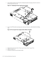
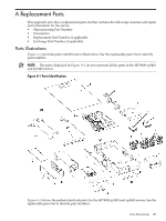
1.
Place the PSI module into the chassis by sliding the module retaining tab into the socket on
the hard disk drive bay wall.
Figure 6-77 Replacing the Power Supply Interface Module
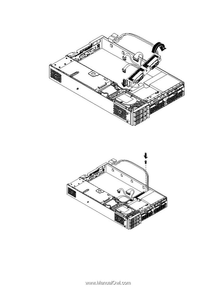
2.
Screw in the PSI module mounting screw and secure the power cables behind the holding
clips.
Figure 6-78 Securing the Power Supply Interface Module and Cables
3.
Replace the system board. (See
“Replacing the System Board” (page 180)
.)
4.
Replace the top cover.
5.
Reconnect all the power and external cables.
188
Removing and Replacing Components