HP rp3440 User Service Guide, Sixth Edition - HP 9000 rp3410/rp3440 - Page 167
Removing the PCI Card Cage, Appendix B
 |
View all HP rp3440 manuals
Add to My Manuals
Save this manual to your list of manuals |
Page 167 highlights
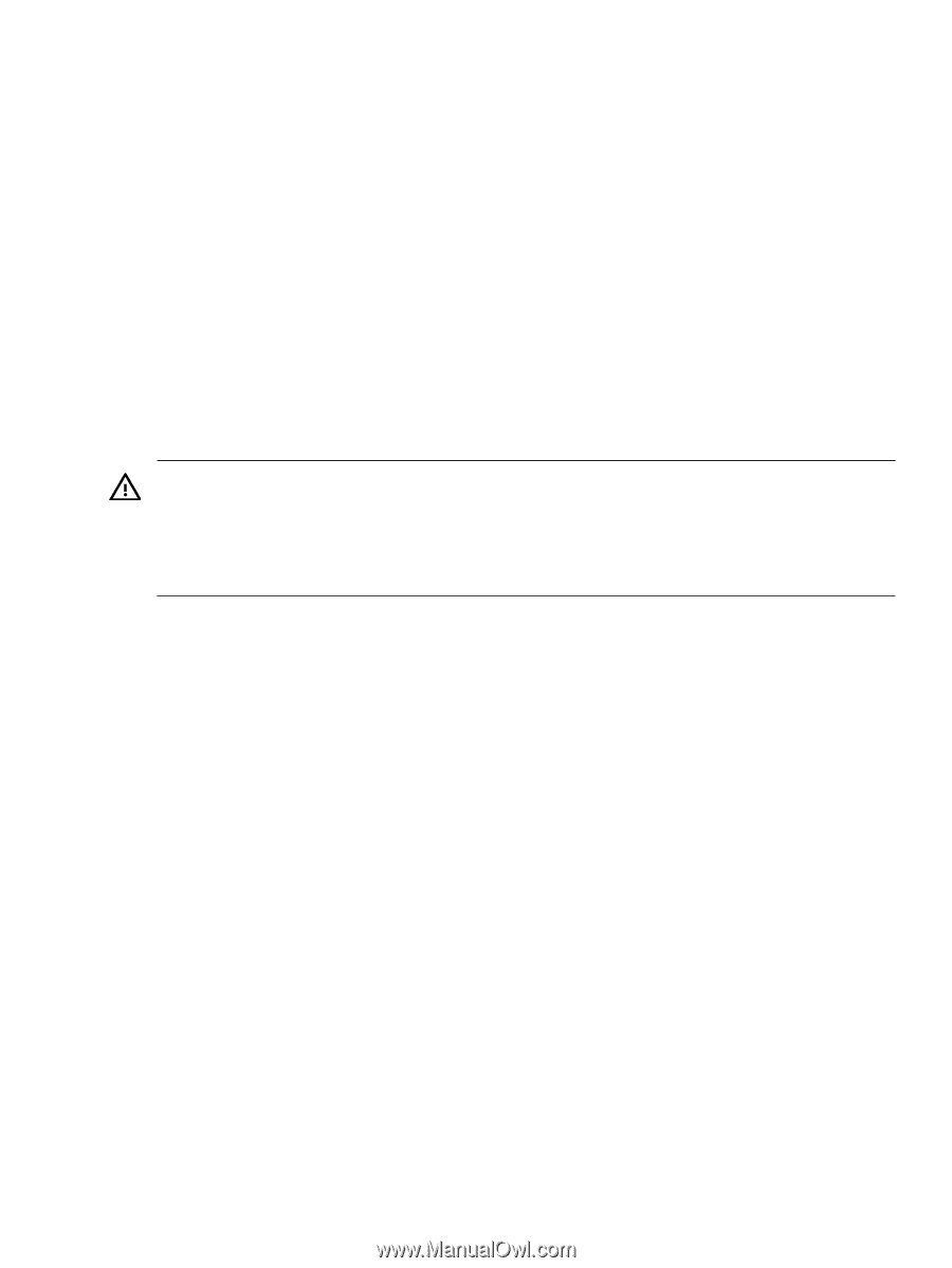
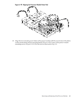
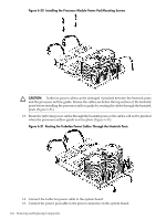
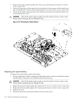
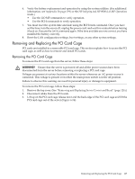
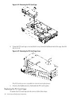
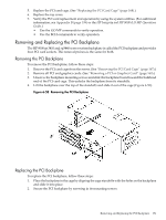
6. Verify the battery replacement and operation by using the system utilities. (For additional information, see Appendix B (page 199) or the HP Integrity and HP 9000 iLO MP Operations Guide.) • Use the iLO MP commands to verify operation. • Use the BCH commands to verify operation. 7. You must reset the system time and date using the BCH DATE command. Once you have set the time, turn the server off, unplug the power cord, and wait for a minute before turning it back on. Execute the DATE command again. If the time and date are now correct, you have installed the battery correctly. 8. Reset the LAN configuration settings, boot settings, or any other system settings. Removing and Replacing the PCI Card Cage PCI cards are installed in a removable PCI card cage. This section explains how to access the PCI card cage, as well as how to remove and install PCI cards. Removing the PCI Card Cage To remove the PCI card cage from the server, follow these steps: WARNING! Ensure that the server is powered off and all the power sources have been disconnected from the server before removing or replacing a PCI card cage. Voltages are present at various locations within the server whenever an AC power source is connected. This voltage is present even when the main power switch is in the off position. Failure to observe this warning can result in personal injury or damage to equipment. To remove the PCI card cage, follow these steps: 1. Remove the top cover. (See "Removing and Replacing Server Covers and Bezel" (page 126).) 2. Disconnect cables from the PCI cards. 3. Lift up on the PCI card cage release lever and the back edge of the PCI card cage and lift the PCI card cage out of the server (Figure 6-54). Removing and Replacing the PCI Card Cage 167
-
 1
1 -
2
-
3
-
4
-
5
-
6
-
7
-
8
-
9
-
10
-
11
-
12
-
13
-
14
-
15
-
16
-
17
-
18
-
19
-
20
-
21
-
22
-
23
-
24
-
25
-
26
-
27
-
28
-
29
-
30
-
31
-
32
-
33
-
34
-
35
-
36
-
37
-
38
-
39
-
40
-
41
-
42
-
43
-
44
-
45
-
46
-
47
-
48
-
49
-
50
-
51
-
52
-
53
-
54
-
55
-
56
-
57
-
58
-
59
-
60
-
61
-
62
-
63
-
64
-
65
-
66
-
67
-
68
-
69
-
70
-
71
-
72
-
73
-
74
-
75
-
76
-
77
-
78
-
79
-
80
-
81
-
82
-
83
-
84
-
85
-
86
-
87
-
88
-
89
-
90
-
91
-
92
-
93
-
94
-
95
-
96
-
97
-
98
-
99
-
100
-
101
-
102
-
103
-
104
-
105
-
106
-
107
-
108
-
109
-
110
-
111
-
112
-
113
-
114
-
115
-
116
-
117
-
118
-
119
-
120
-
121
-
122
-
123
-
124
-
125
-
126
-
127
-
128
-
129
-
130
-
131
-
132
-
133
-
134
-
135
-
136
-
137
-
138
-
139
-
140
-
141
-
142
-
143
-
144
-
145
-
146
-
147
-
148
-
149
-
150
-
151
-
152
-
153
-
154
-
155
-
156
-
157
-
158
-
159
-
160
-
161
-
 162
162 -
 163
163 -
 164
164 -
 165
165 -
 166
166 -
 167
167 -
 168
168 -
 169
169 -
 170
170 -
 171
171 -
 172
172 -
173
-
174
-
175
-
176
-
177
-
178
-
179
-
180
-
181
-
182
-
183
-
184
-
185
-
186
-
187
-
188
-
189
-
190
-
191
-
192
-
193
-
194
-
195
-
196
-
197
-
198
-
199
-
200
-
201
-
202
-
203
-
204
-
205
-
206
-
207
-
208
-
209
-
210
 |
 |