Yamaha DM2000 Owner's Manual - Page 134
Pairing Channels, Pairing Channels by Using the [SEL] Buttons
 |
View all Yamaha DM2000 manuals
Add to My Manuals
Save this manual to your list of manuals |
Page 134 highlights
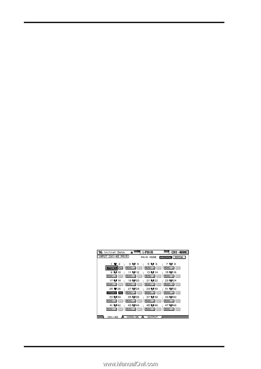
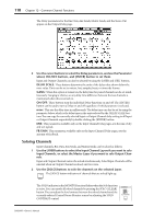
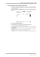
120 Chapter 12-Common Channel Functions Pairing Channels Input Channels, Bus Outs, and Aux Sends can be paired for stereo operation. Input Channels can be paired either horizontally, that is, adjacent odd-even channels on the same Layer (e.g., 1-2, 3-4, 5-6, etc) or vertically, that is, counterpart channels on adjacent Layers (e.g., 1-25, 2-26, 49-73, 50-74, etc). Bus Outs and Aux Sends can be paired only horizontally. Pairing Channels by Using the [SEL] Buttons Only horizontal pairing can be set by using the [SEL] buttons. 1 Use the LAYER buttons to select the Layer containing the channels that you want to pair. 2 While holding down the [SEL] button of the first channel, press the [SEL] but- ton of the second channel. The settings of the first channel are copied to the second channel and the channels are paired. The [SEL] button indicator of the currently selected channel lights up, while the [SEL] button indicator of the other channel flashes. Aux Sends can also be paired by using the AUX SELECT buttons. To cancel a pair, while holding down the [SEL] button of the first channel, press the [SEL] button of the second channel. The following channel parameters are copied, and controlled together, when channels are paired: Fader, On/Off, Insert On/Off, Aux/Matrix On/Off, Aux/Matrix Send Level, Aux/Matrix Pre/Post, Gate parameters, Compressor parameters, Comp Position, EQ parameters, Fader group, Mute group, EQ group, Comp group, Solo, Solo Safe, [AUTO] button, Fade Time, Recall Safe, Bus to Stereo On/Off, Bus to Stereo Level. The following channel parameters are not copied, or controlled together, when channels are paired: Input Patch, Insert Patch, Output Patch, Phase, Delay On/Off, Delay Time, Delay Feedback, Delay Mix, Routing, Pan, Follow Pan, Surround Pan, Bus to Stereo Pan, Aux/Matrix Send Pan, Balance. When channels are paired, the Attenuator value is copied, but the channels are not controlled together. Pairing Channels by Using the Pair Pages Both horizontal and vertical pairing can be set on the Pair pages. 1 Use the DISPLAY ACCESS [PAIR] button to locate the Pair pages. The Pair parameters for the 96 Input Channels are divided between two pages. The Input Channel 1-48 Pair page is shown below. The layout of the other page is the same. DM2000-Owner's Manual
-
 1
1 -
2
-
3
-
4
-
5
-
6
-
7
-
8
-
9
-
10
-
11
-
12
-
13
-
14
-
15
-
16
-
17
-
18
-
19
-
20
-
21
-
22
-
23
-
24
-
25
-
26
-
27
-
28
-
29
-
30
-
31
-
32
-
33
-
34
-
35
-
36
-
37
-
38
-
39
-
40
-
41
-
42
-
43
-
44
-
45
-
46
-
47
-
48
-
49
-
50
-
51
-
52
-
53
-
54
-
55
-
56
-
57
-
58
-
59
-
60
-
61
-
62
-
63
-
64
-
65
-
66
-
67
-
68
-
69
-
70
-
71
-
72
-
73
-
74
-
75
-
76
-
77
-
78
-
79
-
80
-
81
-
82
-
83
-
84
-
85
-
86
-
87
-
88
-
89
-
90
-
91
-
92
-
93
-
94
-
95
-
96
-
97
-
98
-
99
-
100
-
101
-
102
-
103
-
104
-
105
-
106
-
107
-
108
-
109
-
110
-
111
-
112
-
113
-
114
-
115
-
116
-
117
-
118
-
119
-
120
-
121
-
122
-
123
-
124
-
125
-
126
-
127
-
128
-
 129
129 -
 130
130 -
 131
131 -
 132
132 -
 133
133 -
 134
134 -
 135
135 -
 136
136 -
 137
137 -
 138
138 -
 139
139 -
140
-
141
-
142
-
143
-
144
-
145
-
146
-
147
-
148
-
149
-
150
-
151
-
152
-
153
-
154
-
155
-
156
-
157
-
158
-
159
-
160
-
161
-
162
-
163
-
164
-
165
-
166
-
167
-
168
-
169
-
170
-
171
-
172
-
173
-
174
-
175
-
176
-
177
-
178
-
179
-
180
-
181
-
182
-
183
-
184
-
185
-
186
-
187
-
188
-
189
-
190
-
191
-
192
-
193
-
194
-
195
-
196
-
197
-
198
-
199
-
200
-
201
-
202
-
203
-
204
-
205
-
206
-
207
-
208
-
209
-
210
-
211
-
212
-
213
-
214
-
215
-
216
-
217
-
218
-
219
-
220
-
221
-
222
-
223
-
224
-
225
-
226
-
227
-
228
-
229
-
230
-
231
-
232
-
233
-
234
-
235
-
236
-
237
-
238
-
239
-
240
-
241
-
242
-
243
-
244
-
245
-
246
-
247
-
248
-
249
-
250
-
251
-
252
-
253
-
254
-
255
-
256
-
257
-
258
-
259
-
260
-
261
-
262
-
263
-
264
-
265
-
266
-
267
-
268
-
269
-
270
-
271
-
272
-
273
-
274
-
275
-
276
-
277
-
278
-
279
-
280
-
281
-
282
-
283
-
284
-
285
-
286
-
287
-
288
-
289
-
290
-
291
-
292
-
293
-
294
-
295
-
296
-
297
-
298
-
299
-
300
-
301
-
302
-
303
-
304
-
305
-
306
-
307
-
308
-
309
-
310
-
311
-
312
-
313
-
314
-
315
-
316
-
317
-
318
-
319
-
320
-
321
-
322
-
323
-
324
-
325
-
326
-
327
-
328
-
329
-
330
-
331
-
332
-
333
-
334
-
335
-
336
-
337
-
338
-
339
-
340
-
341
-
342
-
343
-
344
-
345
-
346
-
347
-
348
-
349
-
350
-
351
-
352
-
353
-
354
-
355
-
356
-
357
-
358
-
359
-
360
-
361
-
362
 |
 |