Yamaha DM2000 Owner's Manual - Page 32
-48, 49-72 & 73-96 buttons, MASTER button, REMOTE 1-4 buttons, AUTO button, SEL button
 |
View all Yamaha DM2000 manuals
Add to My Manuals
Save this manual to your list of manuals |
Page 32 highlights
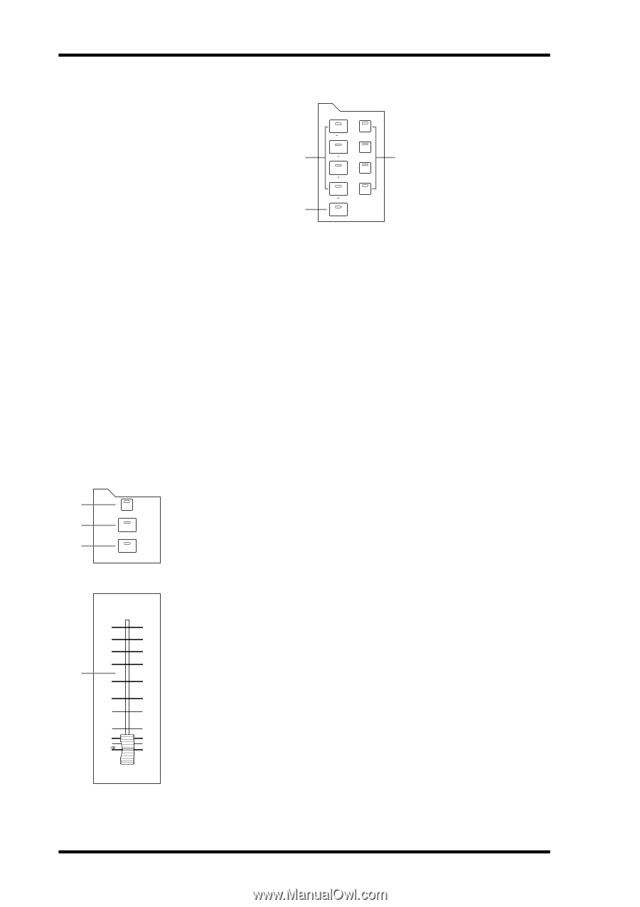
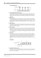
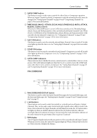
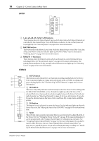
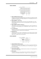
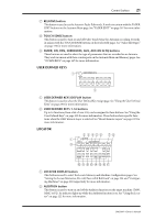
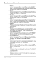
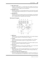
18 Chapter 2-Control Surface & Rear Panel LAYER LAYER 1 2 1 24 REMOTE 1 25 48 REMOTE 2 49 72 REMOTE 3 73 96 REMOTE 4 MASTER 3 A 1-24, 25-48, 49-72 & 73-96 buttons These buttons select the Input Channel Layers, which determine which Input Channels are controlled by the channel strips. The LAYER button indicator for the currently selected Layer lights up. See "Selecting Layers" on page 42 for more information. B MASTER button This button selects the Master Layer, from which the channel strips control Bus Outs, Aux Sends, and Matrix Sends. Its indicator lights up when the Master Layer is selected. See "Selecting Layers" on page 42 for more information. C REMOTE 1-4 buttons These buttons select the Remote Layers, which can be used to control external devices, including DAWs. See "About Remote Layers" on page 217 for more information. The LAYER button indicator for the currently selected Remote Layer lights up. See "Selecting Layers" on page 42 for more information. STEREO STEREO A AUTO button 1 This button is used exclusively to set Automix recording and playback for the Stereo AUTO Out. Its indicator lights up orange in Record-Ready mode, red while recording, and 2 green during playback. See "Channel Strip [AUTO] Buttons" on page 169 for more SEL 3 information. ON B SEL button The Stereo Out [SEL] button is used exclusively to select the Stereo Out for editing with the SELECTED CHANNEL section. Its indicator lights up when the Stereo Out is selected. Each time it's pressed, the selection toggles between the Stereo Out's left and right channels. See "Selecting Channels" on page 43 for more information. It can also 0 be used to add and remove the Stereo Out to and from EQ, Comp, Fader, and Mute 5 groups. 10 15 4 20 C ON button This button is used exclusively to mute the Stereo Out. Its indicator lights up when the Stereo Out is on. See "Muting the Stereo Out (ON/OFF)" on page 83 for more informa- 30 tion. 40 50 D Fader 60 70 This 100 mm touch-sensitive motorized fader is used exclusively to adjust the level of the Stereo Out. See "Setting the Stereo Out Level" on page 83 for more information. It can be grouped with other Output Channel faders for simultaneous operation. See STEREO "Grouping Output Channel Faders" on page 122 for more information. It can also be used to select the Stereo Out, see "Auto Channel Select & Touch Sense Select" on page 44, or to punch the Stereo Out in and out during Automix recording. See "Punch- ing In & Out Individual Parameters" on page 175 for more information. DM2000-Owner's Manual
-
 1
1 -
2
-
3
-
4
-
5
-
6
-
7
-
8
-
9
-
10
-
11
-
12
-
13
-
14
-
15
-
16
-
17
-
18
-
19
-
20
-
21
-
22
-
23
-
24
-
25
-
26
-
 27
27 -
 28
28 -
 29
29 -
 30
30 -
 31
31 -
 32
32 -
 33
33 -
 34
34 -
 35
35 -
 36
36 -
 37
37 -
38
-
39
-
40
-
41
-
42
-
43
-
44
-
45
-
46
-
47
-
48
-
49
-
50
-
51
-
52
-
53
-
54
-
55
-
56
-
57
-
58
-
59
-
60
-
61
-
62
-
63
-
64
-
65
-
66
-
67
-
68
-
69
-
70
-
71
-
72
-
73
-
74
-
75
-
76
-
77
-
78
-
79
-
80
-
81
-
82
-
83
-
84
-
85
-
86
-
87
-
88
-
89
-
90
-
91
-
92
-
93
-
94
-
95
-
96
-
97
-
98
-
99
-
100
-
101
-
102
-
103
-
104
-
105
-
106
-
107
-
108
-
109
-
110
-
111
-
112
-
113
-
114
-
115
-
116
-
117
-
118
-
119
-
120
-
121
-
122
-
123
-
124
-
125
-
126
-
127
-
128
-
129
-
130
-
131
-
132
-
133
-
134
-
135
-
136
-
137
-
138
-
139
-
140
-
141
-
142
-
143
-
144
-
145
-
146
-
147
-
148
-
149
-
150
-
151
-
152
-
153
-
154
-
155
-
156
-
157
-
158
-
159
-
160
-
161
-
162
-
163
-
164
-
165
-
166
-
167
-
168
-
169
-
170
-
171
-
172
-
173
-
174
-
175
-
176
-
177
-
178
-
179
-
180
-
181
-
182
-
183
-
184
-
185
-
186
-
187
-
188
-
189
-
190
-
191
-
192
-
193
-
194
-
195
-
196
-
197
-
198
-
199
-
200
-
201
-
202
-
203
-
204
-
205
-
206
-
207
-
208
-
209
-
210
-
211
-
212
-
213
-
214
-
215
-
216
-
217
-
218
-
219
-
220
-
221
-
222
-
223
-
224
-
225
-
226
-
227
-
228
-
229
-
230
-
231
-
232
-
233
-
234
-
235
-
236
-
237
-
238
-
239
-
240
-
241
-
242
-
243
-
244
-
245
-
246
-
247
-
248
-
249
-
250
-
251
-
252
-
253
-
254
-
255
-
256
-
257
-
258
-
259
-
260
-
261
-
262
-
263
-
264
-
265
-
266
-
267
-
268
-
269
-
270
-
271
-
272
-
273
-
274
-
275
-
276
-
277
-
278
-
279
-
280
-
281
-
282
-
283
-
284
-
285
-
286
-
287
-
288
-
289
-
290
-
291
-
292
-
293
-
294
-
295
-
296
-
297
-
298
-
299
-
300
-
301
-
302
-
303
-
304
-
305
-
306
-
307
-
308
-
309
-
310
-
311
-
312
-
313
-
314
-
315
-
316
-
317
-
318
-
319
-
320
-
321
-
322
-
323
-
324
-
325
-
326
-
327
-
328
-
329
-
330
-
331
-
332
-
333
-
334
-
335
-
336
-
337
-
338
-
339
-
340
-
341
-
342
-
343
-
344
-
345
-
346
-
347
-
348
-
349
-
350
-
351
-
352
-
353
-
354
-
355
-
356
-
357
-
358
-
359
-
360
-
361
-
362
 |
 |