Yamaha DM2000 Owner's Manual - Page 84
Attenuating Input Channels, Gate Edit
 |
View all Yamaha DM2000 manuals
Add to My Manuals
Save this manual to your list of manuals |
Page 84 highlights
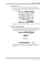
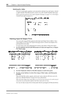
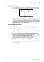
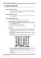
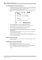
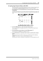
70 Chapter 7-Input Channels 3 Use the SELECTED CHANNEL DYNAMICS [DISPLAY] button to locate the Gate Edit page. 4 Use the cursor buttons to select the parameters, and use the Parameter wheel, INC/DEC buttons, and [ENTER] button to set them. KEYIN SOURCE: This determines the trigger source for the currently selected Input Channel's Gate. Trigger sources include SELF (the Gate's own input signal), CHANNEL (another Input Channel), or AUX (an Aux Send from 1-12). Input Channel trigger sources are selectable in blocks of 12 channels. For example, if Input Channel #1 is currently selected, an Input Channel from 1-12 can be selected as the trigger source. However, if Input Channel #13 is currently selected, an Input Channel from 13-24 can be selected. STEREO LINK: This allows you to pair Gates for stereo operation even when Input Channels are not paired. Input Channel Gates are paired either horizontally or vertically depending on the Pair mode setting for the currently selected Input Channel. See "Pairing Channels" on page 120 for more information on horizontal and vertical pairing. When Input Channels are paired, this parameter is turned on automatically and cannot be changed. CURVE: This displays the gate curve (i.e., input level vs. output level). TYPE: This is the gate type used by the currently selected Input Channel's Gate. Meters: These meters indicate the levels of the currently selected Input Channel and its horizontal or vertical partner. The GR meter indicates the amount of gain reduction being applied by the currently selected Input Channel's Gate. ON/OFF: This turns the currently selected Input Channel's Gate on and off. It works in unison with the SELECTED CHANNEL DYNAMICS [GATE ON] button. PARAMETER: These controls are used to set the Threshold, Range, Attack, Decay, and Hold parameters. Attenuating Input Channels Input Channels signals can be attenuated pre-EQ. See "Attenuating Signals" on page 106 for more information. EQ'ing Input Channels Each Input Channel features 4-band parametric EQ. See "Using EQ" on page 107 for more information. DM2000-Owner's Manual
-
 1
1 -
2
-
3
-
4
-
5
-
6
-
7
-
8
-
9
-
10
-
11
-
12
-
13
-
14
-
15
-
16
-
17
-
18
-
19
-
20
-
21
-
22
-
23
-
24
-
25
-
26
-
27
-
28
-
29
-
30
-
31
-
32
-
33
-
34
-
35
-
36
-
37
-
38
-
39
-
40
-
41
-
42
-
43
-
44
-
45
-
46
-
47
-
48
-
49
-
50
-
51
-
52
-
53
-
54
-
55
-
56
-
57
-
58
-
59
-
60
-
61
-
62
-
63
-
64
-
65
-
66
-
67
-
68
-
69
-
70
-
71
-
72
-
73
-
74
-
75
-
76
-
77
-
78
-
 79
79 -
 80
80 -
 81
81 -
 82
82 -
 83
83 -
 84
84 -
 85
85 -
 86
86 -
 87
87 -
 88
88 -
 89
89 -
90
-
91
-
92
-
93
-
94
-
95
-
96
-
97
-
98
-
99
-
100
-
101
-
102
-
103
-
104
-
105
-
106
-
107
-
108
-
109
-
110
-
111
-
112
-
113
-
114
-
115
-
116
-
117
-
118
-
119
-
120
-
121
-
122
-
123
-
124
-
125
-
126
-
127
-
128
-
129
-
130
-
131
-
132
-
133
-
134
-
135
-
136
-
137
-
138
-
139
-
140
-
141
-
142
-
143
-
144
-
145
-
146
-
147
-
148
-
149
-
150
-
151
-
152
-
153
-
154
-
155
-
156
-
157
-
158
-
159
-
160
-
161
-
162
-
163
-
164
-
165
-
166
-
167
-
168
-
169
-
170
-
171
-
172
-
173
-
174
-
175
-
176
-
177
-
178
-
179
-
180
-
181
-
182
-
183
-
184
-
185
-
186
-
187
-
188
-
189
-
190
-
191
-
192
-
193
-
194
-
195
-
196
-
197
-
198
-
199
-
200
-
201
-
202
-
203
-
204
-
205
-
206
-
207
-
208
-
209
-
210
-
211
-
212
-
213
-
214
-
215
-
216
-
217
-
218
-
219
-
220
-
221
-
222
-
223
-
224
-
225
-
226
-
227
-
228
-
229
-
230
-
231
-
232
-
233
-
234
-
235
-
236
-
237
-
238
-
239
-
240
-
241
-
242
-
243
-
244
-
245
-
246
-
247
-
248
-
249
-
250
-
251
-
252
-
253
-
254
-
255
-
256
-
257
-
258
-
259
-
260
-
261
-
262
-
263
-
264
-
265
-
266
-
267
-
268
-
269
-
270
-
271
-
272
-
273
-
274
-
275
-
276
-
277
-
278
-
279
-
280
-
281
-
282
-
283
-
284
-
285
-
286
-
287
-
288
-
289
-
290
-
291
-
292
-
293
-
294
-
295
-
296
-
297
-
298
-
299
-
300
-
301
-
302
-
303
-
304
-
305
-
306
-
307
-
308
-
309
-
310
-
311
-
312
-
313
-
314
-
315
-
316
-
317
-
318
-
319
-
320
-
321
-
322
-
323
-
324
-
325
-
326
-
327
-
328
-
329
-
330
-
331
-
332
-
333
-
334
-
335
-
336
-
337
-
338
-
339
-
340
-
341
-
342
-
343
-
344
-
345
-
346
-
347
-
348
-
349
-
350
-
351
-
352
-
353
-
354
-
355
-
356
-
357
-
358
-
359
-
360
-
361
-
362
 |
 |