Yamaha DM2000 Owner's Manual - Page 57
Selecting Channels, Stereo Out [SEL] Button
 |
View all Yamaha DM2000 manuals
Add to My Manuals
Save this manual to your list of manuals |
Page 57 highlights
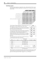
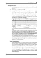
Selecting Channels 43 Selecting Channels To select Input and Output Channels for editing with the SELECTED CHANNEL controls, you use the LAYER buttons to select a Layer, and the [SEL] buttons to select a channel on that Layer. 1 Select a Layer, as explained on page 42. 2 Use the [SEL] buttons to select an Input or Output Channel. The [SEL] button indicator for the currently selected channel lights up, and the SEL border of its channel strip display lights up (see page 39). In addition, the Channel's ID and Short name appear in the upper right corner of the display (see page 36). The exact channel selected by each [SEL] button depends on the currently selected Layer. For example, when Layer 1-24 is selected, [SEL] button #1 selects Input Channel #1. When Layer 25-48 is selected, it selects Input Channel #25. And when the Master Layer is selected, it selects Bus Out #1, as shown in the following table. Layer 1-8 [SEL] Button 9-16 17-20 21-24 1-24 25-48 49-72 73-96 MASTER REMOTE 1-4 Input Channels 1-24 Input Channels 25-48 Input Channels 49-72 Input Channels 73-96 Bus Outs 1-8 Aux Sends 1-12 Matrix Sends 1-41 Operation depends on the selected target. See "About Remote Layers" on page 217 for more information. 1. Each time a [SEL] button is pressed, the selection toggles between the Matrix Send's left and right channels. For paired Input or Output channels, the channel whose [SEL] button you press is selected, and its indicator lights up. The [SEL] button indicator of the other channel flashes. Vertical and horizontal Input and Output channel partners can also be selected by using the SELECTED CHANNEL PAN/SURROUND [L] and [R] buttons, which can also be used to select left and right channels when a Matrix Send or the Stereo Out is selected. If the currently displayed page contains a relevant parameter, when a channel's [SEL] button is pressed, the cursor moves to that parameter automatically. If the currently displayed page contains no such parameter, the page that does contain such a parameter is selected automatically. For example, if a Delay page for the Output Channels is selected when an Input Channel [SEL] button is pressed, the Delay page showing the relevant Input Channel Delay parameter is selected automatically. Stereo Out [SEL] Button The Stereo Out [SEL] button is used exclusively to select the Stereo Out for editing with the SELECTED CHANNEL controls. Its indicator lights up when the Stereo Out is selected. Each time it's pressed, the selection toggles between the Stereo Out's left and right channels. The SELECTED CHANNEL PAN/SURROUND [L] and [R] buttons can also be used to select the left and right channels. If the currently displayed page contains a Stereo Out parameter, that parameter is selected automatically when the Stereo Out [SEL] button is pressed. If the currently selected page contain no such parameter, the page that does contain such a parameter is selected automatically. For example, if a Delay page for the Input Channels is currently selected when the Stereo Out [SEL] button is pressed, the Delay page showing the Stereo Out Delay parameter is selected automatically. DM2000-Owner's Manual
-
 1
1 -
2
-
3
-
4
-
5
-
6
-
7
-
8
-
9
-
10
-
11
-
12
-
13
-
14
-
15
-
16
-
17
-
18
-
19
-
20
-
21
-
22
-
23
-
24
-
25
-
26
-
27
-
28
-
29
-
30
-
31
-
32
-
33
-
34
-
35
-
36
-
37
-
38
-
39
-
40
-
41
-
42
-
43
-
44
-
45
-
46
-
47
-
48
-
49
-
50
-
51
-
 52
52 -
 53
53 -
 54
54 -
 55
55 -
 56
56 -
 57
57 -
 58
58 -
 59
59 -
 60
60 -
 61
61 -
 62
62 -
63
-
64
-
65
-
66
-
67
-
68
-
69
-
70
-
71
-
72
-
73
-
74
-
75
-
76
-
77
-
78
-
79
-
80
-
81
-
82
-
83
-
84
-
85
-
86
-
87
-
88
-
89
-
90
-
91
-
92
-
93
-
94
-
95
-
96
-
97
-
98
-
99
-
100
-
101
-
102
-
103
-
104
-
105
-
106
-
107
-
108
-
109
-
110
-
111
-
112
-
113
-
114
-
115
-
116
-
117
-
118
-
119
-
120
-
121
-
122
-
123
-
124
-
125
-
126
-
127
-
128
-
129
-
130
-
131
-
132
-
133
-
134
-
135
-
136
-
137
-
138
-
139
-
140
-
141
-
142
-
143
-
144
-
145
-
146
-
147
-
148
-
149
-
150
-
151
-
152
-
153
-
154
-
155
-
156
-
157
-
158
-
159
-
160
-
161
-
162
-
163
-
164
-
165
-
166
-
167
-
168
-
169
-
170
-
171
-
172
-
173
-
174
-
175
-
176
-
177
-
178
-
179
-
180
-
181
-
182
-
183
-
184
-
185
-
186
-
187
-
188
-
189
-
190
-
191
-
192
-
193
-
194
-
195
-
196
-
197
-
198
-
199
-
200
-
201
-
202
-
203
-
204
-
205
-
206
-
207
-
208
-
209
-
210
-
211
-
212
-
213
-
214
-
215
-
216
-
217
-
218
-
219
-
220
-
221
-
222
-
223
-
224
-
225
-
226
-
227
-
228
-
229
-
230
-
231
-
232
-
233
-
234
-
235
-
236
-
237
-
238
-
239
-
240
-
241
-
242
-
243
-
244
-
245
-
246
-
247
-
248
-
249
-
250
-
251
-
252
-
253
-
254
-
255
-
256
-
257
-
258
-
259
-
260
-
261
-
262
-
263
-
264
-
265
-
266
-
267
-
268
-
269
-
270
-
271
-
272
-
273
-
274
-
275
-
276
-
277
-
278
-
279
-
280
-
281
-
282
-
283
-
284
-
285
-
286
-
287
-
288
-
289
-
290
-
291
-
292
-
293
-
294
-
295
-
296
-
297
-
298
-
299
-
300
-
301
-
302
-
303
-
304
-
305
-
306
-
307
-
308
-
309
-
310
-
311
-
312
-
313
-
314
-
315
-
316
-
317
-
318
-
319
-
320
-
321
-
322
-
323
-
324
-
325
-
326
-
327
-
328
-
329
-
330
-
331
-
332
-
333
-
334
-
335
-
336
-
337
-
338
-
339
-
340
-
341
-
342
-
343
-
344
-
345
-
346
-
347
-
348
-
349
-
350
-
351
-
352
-
353
-
354
-
355
-
356
-
357
-
358
-
359
-
360
-
361
-
362
 |
 |