Yamaha DM2000 Owner's Manual - Page 29
Pan/surround, Threshold, Range, Attack, Decay, Hold Threshold, Ratio
 |
View all Yamaha DM2000 manuals
Add to My Manuals
Save this manual to your list of manuals |
Page 29 highlights
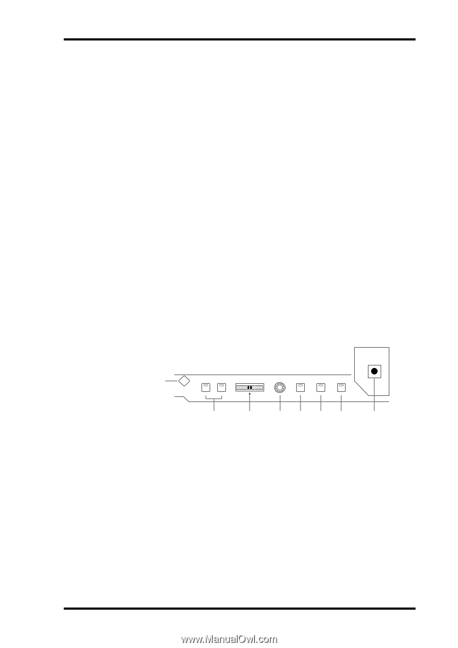
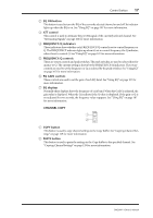
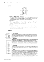
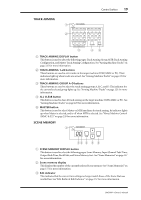
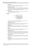
Control Surface 15 B GATE/COMP button This button is used to set the rotary controls for either Gate or Compressor operation. When an Output Channel is selected, Compressor is selected automatically and cannot be changed. See "Gating Input Channels" on page 69 and "Compressing Channels" on page 113 for more information. C THRESHOLD, RANGE, ATTACK, DECAY, HOLD (THRESHOLD, RATIO, ATTACK, RELEASE, GAIN) controls When the GATE/COMP button is set to GATE, these controls set the Threshold, Range, Attack, Decay, and Hold parameters of the currently selected Input Channel's Gate. When it's set to COMP, they set the Threshold, Ratio, Attack, Release, and Gain parameters of the currently selected channel's Compressor. See "Gating Input Channels" on page 69 and "Compressing Channels" on page 113 for more information. D GATE ON button This button is used to turn the currently selected Input Channel's Gate on and off. Its indicator lights up when the Gate is on. See "Gating Input Channels" on page 69 for more information. E COMP ON button This button is used to turn the currently selected channel's Compressor on and off. Its indicator lights up when the Compressor is on. See "Compressing Channels" on page 113 for more information. F GATE/COMP indicators These indicators show whether the rotary controls are set to control either a Gate or a Compressor. The GATE indicator lights up when they're set to control a Gate; the COMP indicator, when they're set to control a Compressor. See "Gating Input Channels" on page 69 and "Compressing Channels" on page 113 for more information. PAN/SURROUND 1 PAN / SURROUND DISPLAY L ODD L R R EVEN LINK GRAB EFFECT 2 3 4567 8 A PAN/SURROUND DISPLAY button This button is used to select the Input Channel Pan pages, the Surround Mode page, and the Surround Edit pages. See "Panning Input Channels" on page 76 and "Using Surround Pan" on page 77. B L & R buttons These buttons can be used to select horizontally or vertically partnered Input or Output Channels. They can be used to select the left and right channels when a Matrix Send or the Stereo Out is selected. For Input Channels, in Individual Pan mode, the [L] button indicator lights up when an odd/left channel is selected; the [R] button indicator, when an even/right channel is selected. In Gang or Inverse Gang Pan mode, the button indicator of the other channel in the pair flashes when its partner is selected. C PAN display This 10-segment display indicates the pan position of the currently selected Input Channel. When pan is set to center, the center two segments light up. When a Matrix Send or the Stereo Out is selected, it displays the balance. DM2000-Owner's Manual
-
 1
1 -
2
-
3
-
4
-
5
-
6
-
7
-
8
-
9
-
10
-
11
-
12
-
13
-
14
-
15
-
16
-
17
-
18
-
19
-
20
-
21
-
22
-
23
-
 24
24 -
 25
25 -
 26
26 -
 27
27 -
 28
28 -
 29
29 -
 30
30 -
 31
31 -
 32
32 -
 33
33 -
 34
34 -
35
-
36
-
37
-
38
-
39
-
40
-
41
-
42
-
43
-
44
-
45
-
46
-
47
-
48
-
49
-
50
-
51
-
52
-
53
-
54
-
55
-
56
-
57
-
58
-
59
-
60
-
61
-
62
-
63
-
64
-
65
-
66
-
67
-
68
-
69
-
70
-
71
-
72
-
73
-
74
-
75
-
76
-
77
-
78
-
79
-
80
-
81
-
82
-
83
-
84
-
85
-
86
-
87
-
88
-
89
-
90
-
91
-
92
-
93
-
94
-
95
-
96
-
97
-
98
-
99
-
100
-
101
-
102
-
103
-
104
-
105
-
106
-
107
-
108
-
109
-
110
-
111
-
112
-
113
-
114
-
115
-
116
-
117
-
118
-
119
-
120
-
121
-
122
-
123
-
124
-
125
-
126
-
127
-
128
-
129
-
130
-
131
-
132
-
133
-
134
-
135
-
136
-
137
-
138
-
139
-
140
-
141
-
142
-
143
-
144
-
145
-
146
-
147
-
148
-
149
-
150
-
151
-
152
-
153
-
154
-
155
-
156
-
157
-
158
-
159
-
160
-
161
-
162
-
163
-
164
-
165
-
166
-
167
-
168
-
169
-
170
-
171
-
172
-
173
-
174
-
175
-
176
-
177
-
178
-
179
-
180
-
181
-
182
-
183
-
184
-
185
-
186
-
187
-
188
-
189
-
190
-
191
-
192
-
193
-
194
-
195
-
196
-
197
-
198
-
199
-
200
-
201
-
202
-
203
-
204
-
205
-
206
-
207
-
208
-
209
-
210
-
211
-
212
-
213
-
214
-
215
-
216
-
217
-
218
-
219
-
220
-
221
-
222
-
223
-
224
-
225
-
226
-
227
-
228
-
229
-
230
-
231
-
232
-
233
-
234
-
235
-
236
-
237
-
238
-
239
-
240
-
241
-
242
-
243
-
244
-
245
-
246
-
247
-
248
-
249
-
250
-
251
-
252
-
253
-
254
-
255
-
256
-
257
-
258
-
259
-
260
-
261
-
262
-
263
-
264
-
265
-
266
-
267
-
268
-
269
-
270
-
271
-
272
-
273
-
274
-
275
-
276
-
277
-
278
-
279
-
280
-
281
-
282
-
283
-
284
-
285
-
286
-
287
-
288
-
289
-
290
-
291
-
292
-
293
-
294
-
295
-
296
-
297
-
298
-
299
-
300
-
301
-
302
-
303
-
304
-
305
-
306
-
307
-
308
-
309
-
310
-
311
-
312
-
313
-
314
-
315
-
316
-
317
-
318
-
319
-
320
-
321
-
322
-
323
-
324
-
325
-
326
-
327
-
328
-
329
-
330
-
331
-
332
-
333
-
334
-
335
-
336
-
337
-
338
-
339
-
340
-
341
-
342
-
343
-
344
-
345
-
346
-
347
-
348
-
349
-
350
-
351
-
352
-
353
-
354
-
355
-
356
-
357
-
358
-
359
-
360
-
361
-
362
 |
 |