Yamaha DM2000 Owner's Manual - Page 90
Panning Input Channels, Using the Encoders, Using the SELECTED CHANNEL PAN/SURROUND Controls
 |
View all Yamaha DM2000 manuals
Add to My Manuals
Save this manual to your list of manuals |
Page 90 highlights
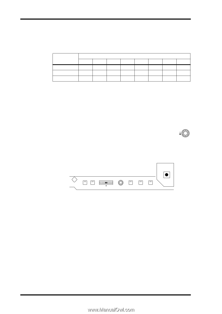
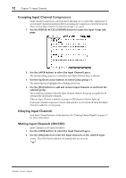
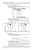
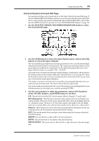
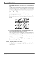
76 Chapter 7-Input Channels The currently selected Surround mode is displayed in the lower-left corner. When Stereo mode is selected, the Bus Out routing buttons display numbers from 1 through 8. When a Surround Pan mode is selected, they display abbreviations of the Surround Channel names, as shown in the following table. See "Using Surround Pan" on page 77 for more information. Bus Outs Surround Mode 1 2 3 4 5 6 7 8 Stereo 1 2 3 4 5 6 7 8 3-1 L R C S 5 6 7 8 5.1 L R Ls Rs C E1 7 8 1. Short for LFE (Low frequency Effects). Panning Input Channels Input Channels can be panned between the left and right channels of the Stereo Out. Using the Encoders 1 Use the LAYER buttons to select the Input Channel Layers. 2 Press the ENCODER MODE [PAN] button to select the Pan Encoder mode. 3 Use the Encoders to pan the input channels. Using the SELECTED CHANNEL PAN/SURROUND Controls 1 Use the LAYER buttons to select the Input Channel Layers, and use the [SEL] buttons to select the Input Channels. PAN / SURROUND DISPLAY L ODD L R R EVEN LINK GRAB EFFECT 2 Use the Pan control to pan the currently selected Input Channel. The pan display indicates the pan position of the currently selected Input Channel. When pan is set to center, the center two segments light up. You can use the [L] and [R] buttons to select horizontal or vertical Input Channel partners. The [LINK] button, which is enabled only when a Surround mode other than Stereo is selected, is used to link the Pan control and the Joystick so that either control can be used for panning. It's a global setting that applies to all Input Channels. For this to work, the [EFFECT] button indicator must be off and the [GRAB] and [LINK] button indicators must be on. Pan Pages Pan settings can be viewed and set on the Pan pages. If the Auto PAN/SURROUND Display preference is on, these pages appear automatically when a control in the SELECTED CHANNEL PAN/SURROUND section is operated. If both the [LINK] and [GRAB] button indicators are on, these pages will also appear when the Joystick is operated. See "Auto PAN/SURROUND Display" on page 234. 1 Use the SELECTED CHANNEL PAN/SURROUND [DISPLAY] button to select the Input Channel Pan pages. DM2000-Owner's Manual
-
 1
1 -
2
-
3
-
4
-
5
-
6
-
7
-
8
-
9
-
10
-
11
-
12
-
13
-
14
-
15
-
16
-
17
-
18
-
19
-
20
-
21
-
22
-
23
-
24
-
25
-
26
-
27
-
28
-
29
-
30
-
31
-
32
-
33
-
34
-
35
-
36
-
37
-
38
-
39
-
40
-
41
-
42
-
43
-
44
-
45
-
46
-
47
-
48
-
49
-
50
-
51
-
52
-
53
-
54
-
55
-
56
-
57
-
58
-
59
-
60
-
61
-
62
-
63
-
64
-
65
-
66
-
67
-
68
-
69
-
70
-
71
-
72
-
73
-
74
-
75
-
76
-
77
-
78
-
79
-
80
-
81
-
82
-
83
-
84
-
 85
85 -
 86
86 -
 87
87 -
 88
88 -
 89
89 -
 90
90 -
 91
91 -
 92
92 -
 93
93 -
 94
94 -
 95
95 -
96
-
97
-
98
-
99
-
100
-
101
-
102
-
103
-
104
-
105
-
106
-
107
-
108
-
109
-
110
-
111
-
112
-
113
-
114
-
115
-
116
-
117
-
118
-
119
-
120
-
121
-
122
-
123
-
124
-
125
-
126
-
127
-
128
-
129
-
130
-
131
-
132
-
133
-
134
-
135
-
136
-
137
-
138
-
139
-
140
-
141
-
142
-
143
-
144
-
145
-
146
-
147
-
148
-
149
-
150
-
151
-
152
-
153
-
154
-
155
-
156
-
157
-
158
-
159
-
160
-
161
-
162
-
163
-
164
-
165
-
166
-
167
-
168
-
169
-
170
-
171
-
172
-
173
-
174
-
175
-
176
-
177
-
178
-
179
-
180
-
181
-
182
-
183
-
184
-
185
-
186
-
187
-
188
-
189
-
190
-
191
-
192
-
193
-
194
-
195
-
196
-
197
-
198
-
199
-
200
-
201
-
202
-
203
-
204
-
205
-
206
-
207
-
208
-
209
-
210
-
211
-
212
-
213
-
214
-
215
-
216
-
217
-
218
-
219
-
220
-
221
-
222
-
223
-
224
-
225
-
226
-
227
-
228
-
229
-
230
-
231
-
232
-
233
-
234
-
235
-
236
-
237
-
238
-
239
-
240
-
241
-
242
-
243
-
244
-
245
-
246
-
247
-
248
-
249
-
250
-
251
-
252
-
253
-
254
-
255
-
256
-
257
-
258
-
259
-
260
-
261
-
262
-
263
-
264
-
265
-
266
-
267
-
268
-
269
-
270
-
271
-
272
-
273
-
274
-
275
-
276
-
277
-
278
-
279
-
280
-
281
-
282
-
283
-
284
-
285
-
286
-
287
-
288
-
289
-
290
-
291
-
292
-
293
-
294
-
295
-
296
-
297
-
298
-
299
-
300
-
301
-
302
-
303
-
304
-
305
-
306
-
307
-
308
-
309
-
310
-
311
-
312
-
313
-
314
-
315
-
316
-
317
-
318
-
319
-
320
-
321
-
322
-
323
-
324
-
325
-
326
-
327
-
328
-
329
-
330
-
331
-
332
-
333
-
334
-
335
-
336
-
337
-
338
-
339
-
340
-
341
-
342
-
343
-
344
-
345
-
346
-
347
-
348
-
349
-
350
-
351
-
352
-
353
-
354
-
355
-
356
-
357
-
358
-
359
-
360
-
361
-
362
 |
 |