Yamaha DM2000 Owner's Manual - Page 333
Midi Data Format, Format Details, Channel Message, System Common Message, System Realtime Message - digital mixer
 |
View all Yamaha DM2000 manuals
Add to My Manuals
Save this manual to your list of manuals |
Page 333 highlights
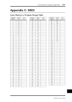
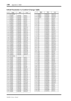
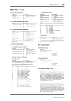
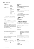
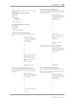
MIDI Data Format 319 MIDI Data Format 1. CHANNEL MESSAGE Command 8n NOTE OFF 9n NOTE ON Bn CONTROL CHANGE Cn PROGRAM CHANGE rx/tx rx rx rx/tx rx/tx function Control the internal effects Control the internal effects Control parameters Switch scene memories 2. SYSTEM COMMON MESSAGE Command F1 MIDI TIME CODE QUARTER FRAME F2 SONG POSITION POINTER rx/tx rx rx function Used when TIME REFERENCE is MIDI CLOCK. Used when TIME REFERENCE is MIDI CLOCK. 3. SYSTEM REALTIME MESSAGE Command F8 TIMING CLOCK FA START FB CONTINUE FC STOP FE ACTIVE SENSING FF RESET rx/tx rx rx* rx* rx* rx rx function MIDI clock Start automix (from the beginning) Start automix (from the middle) Stop automix Check MIDI cable connections Clear running status Received only when the Automix TIME REFERENCE setting is MIDI CLOCK. 4. EXCLUSIVE MESSAGE 4.1 Real Time System Exclusive Command F0 7F dd 06 MMC COMMAND F0 7F dd 07 MMC RESPONSE F0 7F dd 01 MIDI TIME CODE rx/tx tx rx rx function MMC command (refer to MMC specification) MMC response (refer to MMC specification) Used when TIME REFERENCE is MTC. 4.2 System Exclusive Message 4.2.1 Bulk Dump Command rx/tx F0 43 0n 7E BULK DUMP DATA rx/tx F0 43 2n 7E BULK DUMP REQUEST rx/tx function BULK DUMP DATA BULK DUMP REQUEST The following data types of bulk dump are used on the DM2000. Data name 'm' 'S' 'a' 'R' 'O' 'H' 'G' 'Y' 'Q' 'E' 'F' 'J' 'K' 'P' 'C' 'L' 'I' 'V' 'N' tx/rx tx/rx tx/rx tx/rx tx/rx tx/rx tx/rx tx/rx tx/rx tx/rx tx/rx tx/rx tx/rx tx/rx tx/rx tx/rx tx/rx tx/rx tx/rx tx/rx function Scene Memory & Request Setup Memory & Request Automix data & Request Input patch library & Request Output patch library & Request Channel library & Request Gate library & Request Compressor library & Request Equalizer library & Request Effect library & Request GEQ library & Request Bus to Stereo library & Request Surround Monitor library & Request Program change table & Request Control change table & Request User define layer & Request Plug-in User define & Request User define key & Request Plug-in Effect Card Data & Request 4.2.2 PARAMETER CHANGE Command F0 43 1n 3E 06 PARAMETER CHANGE F0 43 3n 3E 06 PARAMETER REQUEST F0 43 1n 3E 7F PARAMETER CHANGE F0 43 3n 3E 7F PARAMETER REQUEST rx/tx rx/tx rx/tx rx/tx rx/tx function DM2000-specific parameter change DM2000-specific parameter request General purpose digital mixer parameter change General purpose digital mixer parameter request The following data types of parameter change are used by the DM2000. Type 1 2 3 4 16 32 33 34 tx/rx tx/rx tx/rx tx/rx tx/rx tx/rx tx/rx tx/rx tx/rx function Edit buffer Patch data Setup data Backup data Function (recall, store, title, pair) Key remote remote meter remote counter 4.2.3 Card Filer Command F0 43 5n CARD FILER rx/tx rx/tx Function Packet for card filer (refer to Card Filer specification) ** tx means that the data can be transmitted from the DM2000. rx means that the data can be received by the DM2000. Format Details 1. NOTE OFF (8n) Reception Received when the [Rx CH] matches. Used to control effects. STATUS DATA 1000nnnn 8n Note off message 0nnnnnnn nn Note number 0vvvvvvv vv Velocity (ignored) 2. NOTE ON (9n) Reception Received when the [Rx CH] matches. Used to control effects. STATUS DATA 1001nnnn 9n Note on message 0nnnnnnn nn Note number 0vvvvvvv vv Velocity (1-127:on, 0:off) 3. CONTROL CHANGE (Bn) Reception Received when [Control Change Rx] is ON and the [Rx CH] matches. However if [OMNI] is ON, this is received regardless of the channel. If [Control Change ECHO] is ON, these messages are echoed to MIDI OUT. If [TABLE] is selected, parameters will be controlled according to the settings of the [Control assign table]. The parameters that can be set are defined in the CONTROL CHANGE ASSIGN PARAMETER LIST. If [NRPN] is selected, four messages are used to control the defined parameter: NRPN control numbers (62h, 63h) and DATA ENTRY control numbers (06h, 26h). Parameter settings are defined in the CONTROL CHANGE ASSIGN PARAMETER LIST. Transmission If [TABLE] is selected, operating the parameters specified in the [Control assign table] will cause these messages to be transmitted on the [Tx CH] if [Control Change TX] is ON. The parameters that can be specified are defined in the CONTROL CHANGE ASSIGN PARAMETER LIST. If [NRPN] is selected, operating the specified parameters will cause data to be transmitted on the [Tx CH] if [Control Change TX] is ON, using four messages: NRPN control numbers (62h, 63h) and DATA ENTRY control numbers (06h, 26h). Parameter settings are defined in the CONTROL CHANGE ASSIGN PARAMETER LIST. DM2000-Owner's Manual
-
 1
1 -
2
-
3
-
4
-
5
-
6
-
7
-
8
-
9
-
10
-
11
-
12
-
13
-
14
-
15
-
16
-
17
-
18
-
19
-
20
-
21
-
22
-
23
-
24
-
25
-
26
-
27
-
28
-
29
-
30
-
31
-
32
-
33
-
34
-
35
-
36
-
37
-
38
-
39
-
40
-
41
-
42
-
43
-
44
-
45
-
46
-
47
-
48
-
49
-
50
-
51
-
52
-
53
-
54
-
55
-
56
-
57
-
58
-
59
-
60
-
61
-
62
-
63
-
64
-
65
-
66
-
67
-
68
-
69
-
70
-
71
-
72
-
73
-
74
-
75
-
76
-
77
-
78
-
79
-
80
-
81
-
82
-
83
-
84
-
85
-
86
-
87
-
88
-
89
-
90
-
91
-
92
-
93
-
94
-
95
-
96
-
97
-
98
-
99
-
100
-
101
-
102
-
103
-
104
-
105
-
106
-
107
-
108
-
109
-
110
-
111
-
112
-
113
-
114
-
115
-
116
-
117
-
118
-
119
-
120
-
121
-
122
-
123
-
124
-
125
-
126
-
127
-
128
-
129
-
130
-
131
-
132
-
133
-
134
-
135
-
136
-
137
-
138
-
139
-
140
-
141
-
142
-
143
-
144
-
145
-
146
-
147
-
148
-
149
-
150
-
151
-
152
-
153
-
154
-
155
-
156
-
157
-
158
-
159
-
160
-
161
-
162
-
163
-
164
-
165
-
166
-
167
-
168
-
169
-
170
-
171
-
172
-
173
-
174
-
175
-
176
-
177
-
178
-
179
-
180
-
181
-
182
-
183
-
184
-
185
-
186
-
187
-
188
-
189
-
190
-
191
-
192
-
193
-
194
-
195
-
196
-
197
-
198
-
199
-
200
-
201
-
202
-
203
-
204
-
205
-
206
-
207
-
208
-
209
-
210
-
211
-
212
-
213
-
214
-
215
-
216
-
217
-
218
-
219
-
220
-
221
-
222
-
223
-
224
-
225
-
226
-
227
-
228
-
229
-
230
-
231
-
232
-
233
-
234
-
235
-
236
-
237
-
238
-
239
-
240
-
241
-
242
-
243
-
244
-
245
-
246
-
247
-
248
-
249
-
250
-
251
-
252
-
253
-
254
-
255
-
256
-
257
-
258
-
259
-
260
-
261
-
262
-
263
-
264
-
265
-
266
-
267
-
268
-
269
-
270
-
271
-
272
-
273
-
274
-
275
-
276
-
277
-
278
-
279
-
280
-
281
-
282
-
283
-
284
-
285
-
286
-
287
-
288
-
289
-
290
-
291
-
292
-
293
-
294
-
295
-
296
-
297
-
298
-
299
-
300
-
301
-
302
-
303
-
304
-
305
-
306
-
307
-
308
-
309
-
310
-
311
-
312
-
313
-
314
-
315
-
316
-
317
-
318
-
319
-
320
-
321
-
322
-
323
-
324
-
325
-
326
-
327
-
 328
328 -
 329
329 -
 330
330 -
 331
331 -
 332
332 -
 333
333 -
 334
334 -
 335
335 -
 336
336 -
 337
337 -
 338
338 -
339
-
340
-
341
-
342
-
343
-
344
-
345
-
346
-
347
-
348
-
349
-
350
-
351
-
352
-
353
-
354
-
355
-
356
-
357
-
358
-
359
-
360
-
361
-
362
 |
 |