Yamaha DM2000 Owner's Manual - Page 46
Digital I/O & Control SMPTE TIME CODE INPUT connector
 |
View all Yamaha DM2000 manuals
Add to My Manuals
Save this manual to your list of manuals |
Page 46 highlights
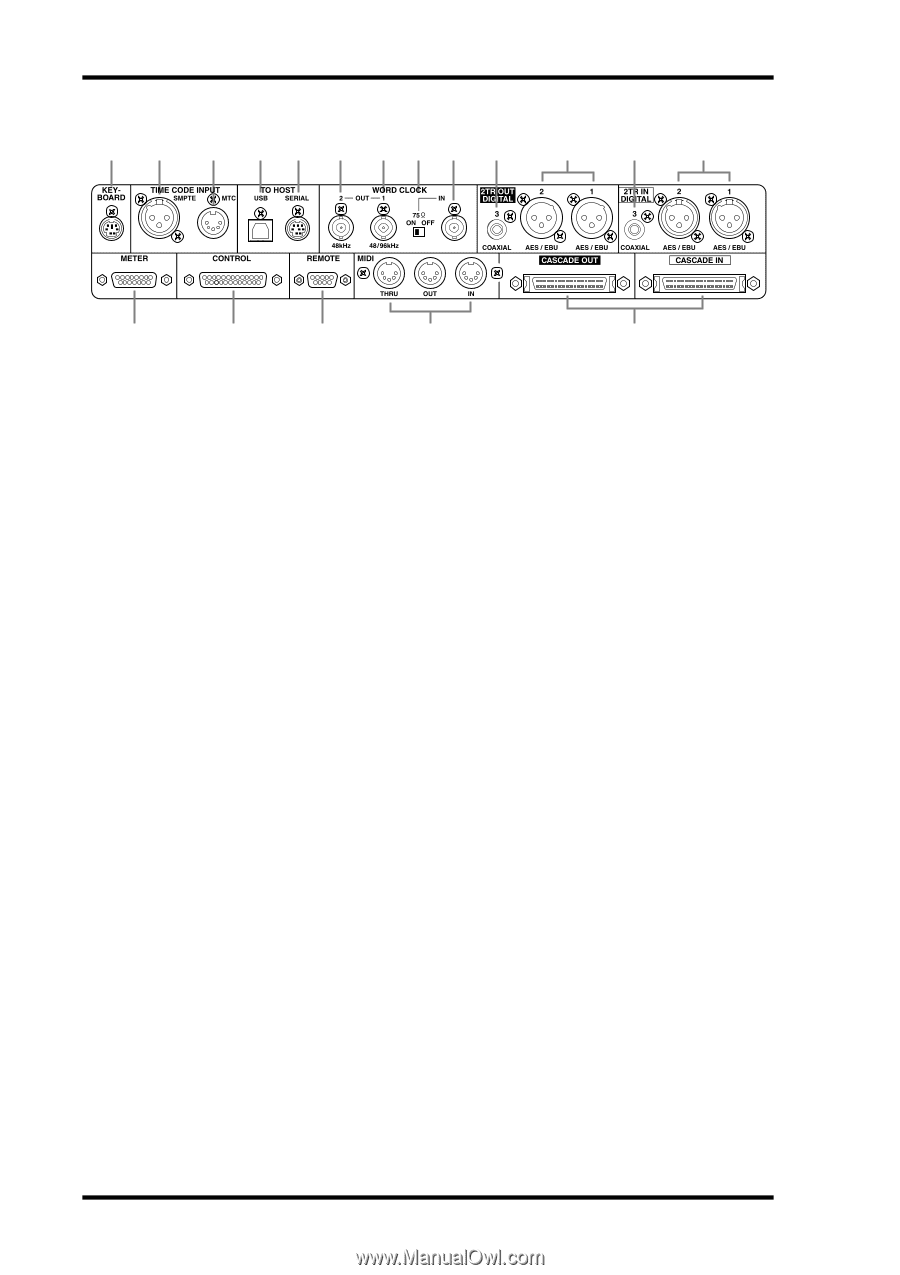
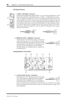
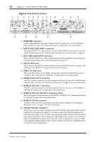
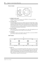
32 Chapter 2-Control Surface & Rear Panel Digital I/O & Control Section 1 2 3 4 5 6 789 J K L M N O P Q R A KEYBOARD connector A PS/2 compatible keyboard can be connected here for quick entry of scene and library titles and channel names. See "Using a Keyboard" on page 38 for more information. B SMPTE TIME CODE INPUT connector This balanced XLR-3-31-type connector is used to input SMPTE timecode for synchronizing the Automix function. See "Selecting the Timecode Source & Frame Rate" on page 171. C MTC TIME CODE INPUT connector This 5-pin DIN connector is used to input MTC for synchronizing the Automix function. See "Selecting the Timecode Source & Frame Rate" on page 171. D USB TO HOST port This USB port is for MIDI communication between the DM2000 and a host computer with a USB port. See "MIDI I/O" on page 182 for more information. E SERIAL TO HOST port This 8-pin mini DIN port is for MIDI communication between the DM2000 and a host computer with a serial port. See "MIDI I/O" on page 182 for more information. F WORD CLOCK OUT 2 connector This BNC connector outputs a wordclock signal at half the clock rate of the DM2000 when using 88.2 kHz or 96 kHz. See "Wordclock Connections" on page 50 for more information. G WORD CLOCK OUT 1 connector This BNC connector outputs a wordclock signal at the same clock rate as the DM2000. See "Wordclock Connections" on page 50 for more information. H WORD CLOCK 75Ω ON/OFF termination switch This switch applies 75Ω termination to the WORD CLOCK IN. See "Terminating External Wordclocks" on page 52 for more information. I WORD CLOCK IN connector This BNC connector is for connecting an external wordclock signal. See "Selecting the Wordclock Source" on page 51 for more information. J 2TR OUT DIGITAL COAXIAL 3 This phono connector outputs consumer format (IEC-60958) digital audio, and is typically connected to the digital stereo input of a 2-track recorder. The following signals can be patched to this output: Stereo Out, Bus Outs, Aux Sends, Matrix Sends, Direct Outs, Insert Outs, and Control Room. The sampling rate of the digital audio output can be set independently of the DM2000 sampling rate by using the internal sampling rate converter. Dither can be applied for digital audio transfer to lower-resolution systems. See "2TR Digital Outs" on page 52 for more information. DM2000-Owner's Manual
-
 1
1 -
2
-
3
-
4
-
5
-
6
-
7
-
8
-
9
-
10
-
11
-
12
-
13
-
14
-
15
-
16
-
17
-
18
-
19
-
20
-
21
-
22
-
23
-
24
-
25
-
26
-
27
-
28
-
29
-
30
-
31
-
32
-
33
-
34
-
35
-
36
-
37
-
38
-
39
-
40
-
 41
41 -
 42
42 -
 43
43 -
 44
44 -
 45
45 -
 46
46 -
 47
47 -
 48
48 -
 49
49 -
 50
50 -
 51
51 -
52
-
53
-
54
-
55
-
56
-
57
-
58
-
59
-
60
-
61
-
62
-
63
-
64
-
65
-
66
-
67
-
68
-
69
-
70
-
71
-
72
-
73
-
74
-
75
-
76
-
77
-
78
-
79
-
80
-
81
-
82
-
83
-
84
-
85
-
86
-
87
-
88
-
89
-
90
-
91
-
92
-
93
-
94
-
95
-
96
-
97
-
98
-
99
-
100
-
101
-
102
-
103
-
104
-
105
-
106
-
107
-
108
-
109
-
110
-
111
-
112
-
113
-
114
-
115
-
116
-
117
-
118
-
119
-
120
-
121
-
122
-
123
-
124
-
125
-
126
-
127
-
128
-
129
-
130
-
131
-
132
-
133
-
134
-
135
-
136
-
137
-
138
-
139
-
140
-
141
-
142
-
143
-
144
-
145
-
146
-
147
-
148
-
149
-
150
-
151
-
152
-
153
-
154
-
155
-
156
-
157
-
158
-
159
-
160
-
161
-
162
-
163
-
164
-
165
-
166
-
167
-
168
-
169
-
170
-
171
-
172
-
173
-
174
-
175
-
176
-
177
-
178
-
179
-
180
-
181
-
182
-
183
-
184
-
185
-
186
-
187
-
188
-
189
-
190
-
191
-
192
-
193
-
194
-
195
-
196
-
197
-
198
-
199
-
200
-
201
-
202
-
203
-
204
-
205
-
206
-
207
-
208
-
209
-
210
-
211
-
212
-
213
-
214
-
215
-
216
-
217
-
218
-
219
-
220
-
221
-
222
-
223
-
224
-
225
-
226
-
227
-
228
-
229
-
230
-
231
-
232
-
233
-
234
-
235
-
236
-
237
-
238
-
239
-
240
-
241
-
242
-
243
-
244
-
245
-
246
-
247
-
248
-
249
-
250
-
251
-
252
-
253
-
254
-
255
-
256
-
257
-
258
-
259
-
260
-
261
-
262
-
263
-
264
-
265
-
266
-
267
-
268
-
269
-
270
-
271
-
272
-
273
-
274
-
275
-
276
-
277
-
278
-
279
-
280
-
281
-
282
-
283
-
284
-
285
-
286
-
287
-
288
-
289
-
290
-
291
-
292
-
293
-
294
-
295
-
296
-
297
-
298
-
299
-
300
-
301
-
302
-
303
-
304
-
305
-
306
-
307
-
308
-
309
-
310
-
311
-
312
-
313
-
314
-
315
-
316
-
317
-
318
-
319
-
320
-
321
-
322
-
323
-
324
-
325
-
326
-
327
-
328
-
329
-
330
-
331
-
332
-
333
-
334
-
335
-
336
-
337
-
338
-
339
-
340
-
341
-
342
-
343
-
344
-
345
-
346
-
347
-
348
-
349
-
350
-
351
-
352
-
353
-
354
-
355
-
356
-
357
-
358
-
359
-
360
-
361
-
362
 |
 |