Yamaha DM2000 Owner's Manual - Page 146
Monitoring & Talkback, Control Room Monitoring
 |
View all Yamaha DM2000 manuals
Add to My Manuals
Save this manual to your list of manuals |
Page 146 highlights
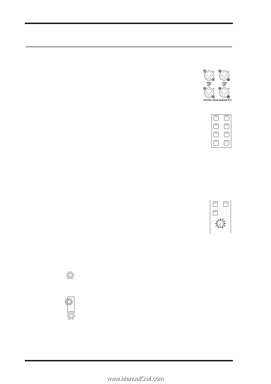
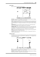
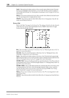
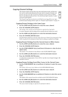
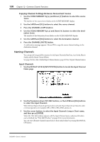
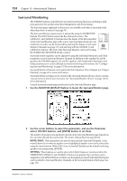
132 Chapter 13-Monitoring & Talkback 13 Monitoring & Talkback Control Room Monitoring The DM2000 features independent outputs and level controls for two sets of studio monitors. The LARGE CONTROL ROOM MONITOR OUT +4 dB (BAL) XLR-3-32-type connectors are intended to feed to the control room's main monitors. The SMALL CONTROL ROOM MONITOR OUT +4 dB (BAL) XLR-3-32-type connectors are intended to feed to the control room's nearfield monitors. The Control Room Monitor signal source is selected by using the CONTROL ROOM STEREO buttons. [2TR D1]: Selects the 2TR IN DIGITAL AES/EBU 1. [2TR D2]: Selects the 2TR IN DIGITAL AES/EBU 2. STEREO 2TR D1 2TR A1 2TR D2 2TR A2 [2TR D3]: Selects the 2TR IN DIGITAL COAXIAL 3. 2TR D3 STEREO [2TR A1]: Selects the 2TR IN ANALOG 1. ASSIGN 1 ASSIGN 2 [2TR A2]: Selects the 2TR IN ANALOG 2. [STEREO]: Selects the Stereo Out. [ASSIGN 1]: Selects the Output Channel assigned to this button on the Control Room Setup page. See "Control Room Setup" on page 133. [ASSIGN 2]: Selects the Output Channel assigned to this button on the Control Room Setup page. See "Control Room Setup" on page 133. The level of the Control Room Monitor signal can be set by using the CONTROL ROOM LEVEL control. You can toggle between the LARGE CONTROL ROOM MONITOR OUT and SMALL CONTROL ROOM MONITOR OUT by using the CONTROL ROOM [SMALL] button, whose indicator is off when LARGE is selected, and on when SMALL is selected. The Control Room Monitor signal can be switched into mono by using the CONTROL ROOM [MONO] button. The [DIMMER] button activates the Dimmer function, which dims the Control Room Monitor and Surround Monitor signals by the amount specified on the Control Room Setup page (page 133). The Dimmer function is activated automatically when the Slate, Talkback, or Oscillator function is active. MONO DIMMER SMALL 0 10 CONTROL ROOM LEVEL The level of the SMALL CONTROL ROOM MONITOR OUT can be set by using the SMALL TRIM control. When set at maximum, the level is the same as that of the 0 10 SMALL TRIM LARGE CONTROL ROOM MONITOR OUT. The Control Room Monitor signal is also fed to the PHONES jack, the level of which is set by using the PHONES LEVEL control. PHONES 0 10 PHONES LEVEL DM2000-Owner's Manual
-
 1
1 -
2
-
3
-
4
-
5
-
6
-
7
-
8
-
9
-
10
-
11
-
12
-
13
-
14
-
15
-
16
-
17
-
18
-
19
-
20
-
21
-
22
-
23
-
24
-
25
-
26
-
27
-
28
-
29
-
30
-
31
-
32
-
33
-
34
-
35
-
36
-
37
-
38
-
39
-
40
-
41
-
42
-
43
-
44
-
45
-
46
-
47
-
48
-
49
-
50
-
51
-
52
-
53
-
54
-
55
-
56
-
57
-
58
-
59
-
60
-
61
-
62
-
63
-
64
-
65
-
66
-
67
-
68
-
69
-
70
-
71
-
72
-
73
-
74
-
75
-
76
-
77
-
78
-
79
-
80
-
81
-
82
-
83
-
84
-
85
-
86
-
87
-
88
-
89
-
90
-
91
-
92
-
93
-
94
-
95
-
96
-
97
-
98
-
99
-
100
-
101
-
102
-
103
-
104
-
105
-
106
-
107
-
108
-
109
-
110
-
111
-
112
-
113
-
114
-
115
-
116
-
117
-
118
-
119
-
120
-
121
-
122
-
123
-
124
-
125
-
126
-
127
-
128
-
129
-
130
-
131
-
132
-
133
-
134
-
135
-
136
-
137
-
138
-
139
-
140
-
 141
141 -
 142
142 -
 143
143 -
 144
144 -
 145
145 -
 146
146 -
 147
147 -
 148
148 -
 149
149 -
 150
150 -
 151
151 -
152
-
153
-
154
-
155
-
156
-
157
-
158
-
159
-
160
-
161
-
162
-
163
-
164
-
165
-
166
-
167
-
168
-
169
-
170
-
171
-
172
-
173
-
174
-
175
-
176
-
177
-
178
-
179
-
180
-
181
-
182
-
183
-
184
-
185
-
186
-
187
-
188
-
189
-
190
-
191
-
192
-
193
-
194
-
195
-
196
-
197
-
198
-
199
-
200
-
201
-
202
-
203
-
204
-
205
-
206
-
207
-
208
-
209
-
210
-
211
-
212
-
213
-
214
-
215
-
216
-
217
-
218
-
219
-
220
-
221
-
222
-
223
-
224
-
225
-
226
-
227
-
228
-
229
-
230
-
231
-
232
-
233
-
234
-
235
-
236
-
237
-
238
-
239
-
240
-
241
-
242
-
243
-
244
-
245
-
246
-
247
-
248
-
249
-
250
-
251
-
252
-
253
-
254
-
255
-
256
-
257
-
258
-
259
-
260
-
261
-
262
-
263
-
264
-
265
-
266
-
267
-
268
-
269
-
270
-
271
-
272
-
273
-
274
-
275
-
276
-
277
-
278
-
279
-
280
-
281
-
282
-
283
-
284
-
285
-
286
-
287
-
288
-
289
-
290
-
291
-
292
-
293
-
294
-
295
-
296
-
297
-
298
-
299
-
300
-
301
-
302
-
303
-
304
-
305
-
306
-
307
-
308
-
309
-
310
-
311
-
312
-
313
-
314
-
315
-
316
-
317
-
318
-
319
-
320
-
321
-
322
-
323
-
324
-
325
-
326
-
327
-
328
-
329
-
330
-
331
-
332
-
333
-
334
-
335
-
336
-
337
-
338
-
339
-
340
-
341
-
342
-
343
-
344
-
345
-
346
-
347
-
348
-
349
-
350
-
351
-
352
-
353
-
354
-
355
-
356
-
357
-
358
-
359
-
360
-
361
-
362
 |
 |