Yamaha DM2000 Owner's Manual - Page 21
Aux Select, Encoder Mode
 |
View all Yamaha DM2000 manuals
Add to My Manuals
Save this manual to your list of manuals |
Page 21 highlights
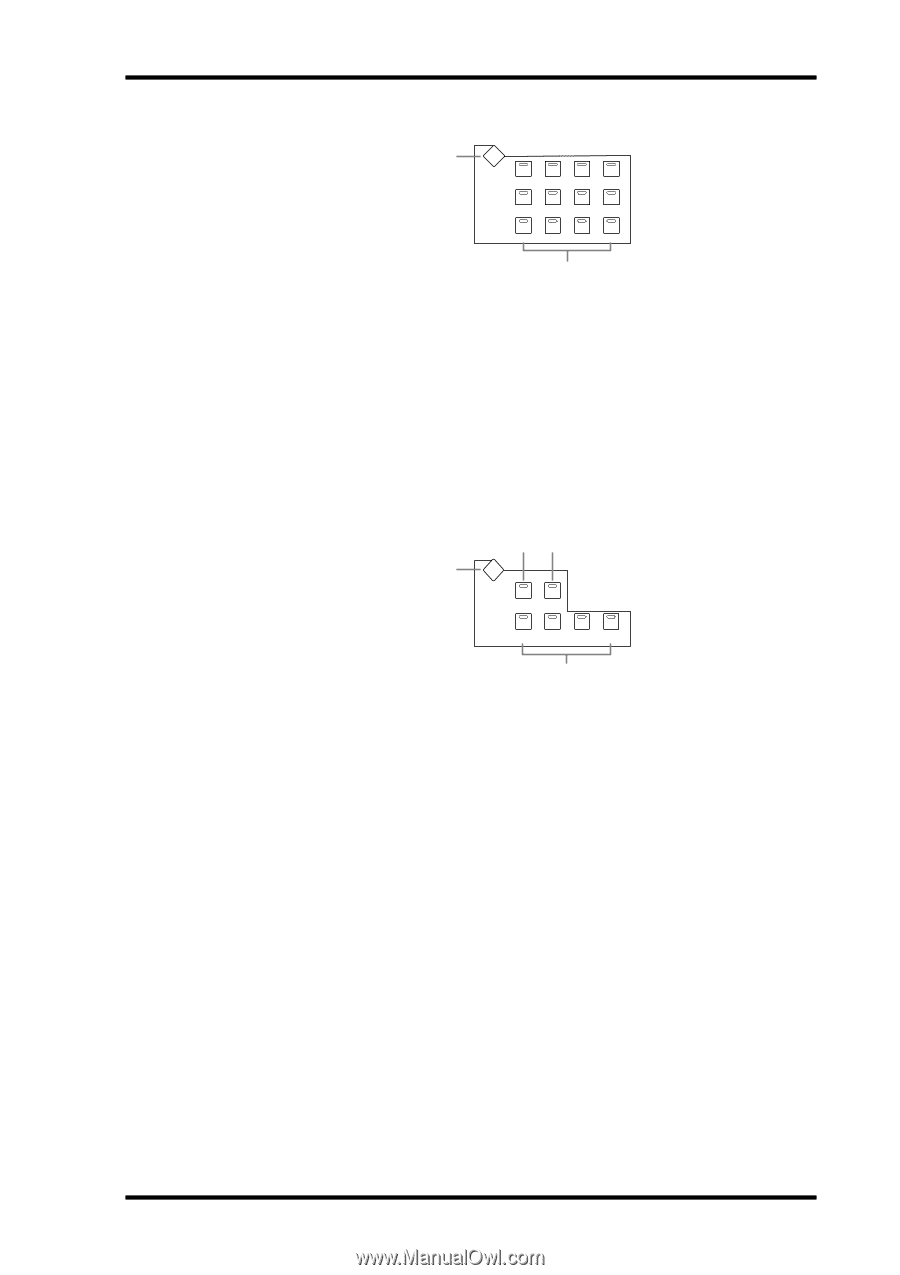
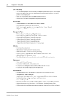
Control Surface 7 AUX SELECT 1 AUX SELECT DISPLAY AUX 1 AUX 2 AUX 3 AUX 4 AUX 5 AUX 6 AUX 7 AUX 8 AUX 9 AUX 10 AUX 11 AUX 12 2 A AUX SELECT DISPLAY button This button is used to select the following pages: Aux Send, Aux Send Pan, and Input Channel Aux View. See "Aux Sends" on page 88 for more information. B AUX 1-12 buttons These buttons are used to select Aux Sends when sending Input Channel signals to Aux Sends. The button indicator of the currently selected Aux Send lights up. If the currently selected Aux Send is paired, the indicator of its partner flashes. See "Aux Sends" on page 88 for more information. These buttons can also be used to pair Aux Sends. See "Pairing Channels" on page 120 for more information. ENCODER MODE 1 23 ENCODER MODE DISPLAY PAN PAN AUX/ MTRX SEND LEVEL ASSIGN 1 ASSIGN 2 ASSIGN 3 ASSIGN 4 INPUT OUTPUT SEND ASSIGN INSERT 4 The small text labels below the ASSIGN buttons apply to the DAW Remote Layer. See "About Remote Layers" on page 217 for more information. A ENCODER MODE DISPLAY button This button is used to select the Encoder Mode Assign page. See "Selecting Encoder Modes" on page 45 for more information. B PAN button This button is used to select the Pan Encoder mode. Its indicator lights up when this mode is selected. In this mode, the Encoders function as Pan controls when an Input Channel Layer is selected. When the Master Layer is selected, Encoders 21-24 function as Matrix Send Balance controls. The other Encoders are inactive. See "Selecting Encoder Modes" on page 45 for more information. C AUX/MTRX button This button is used to select the Aux/Mtrx Encoder mode. Its indicator lights up when this mode is selected. In this mode, the Encoders function as Aux Send level controls when an Input Channel Layer is selected. When the Master Layer is selected, Encoders 1-20 function as Matrix Send level controls. See "Selecting Encoder Modes" on page 45. D ASSIGN 1-4 buttons These buttons are used to select the assignable Encoder modes. The button indicator for the currently selected mode lights up. When an assignable mode is selected, the function of the Encoders depends on the assigned parameter. Up to four parameters, from a list of over 40, can be assigned to these four buttons. See "Assigning Parameters to the ENCODER MODE Assign Buttons" on page 46 for more information. DM2000-Owner's Manual
-
 1
1 -
2
-
3
-
4
-
5
-
6
-
7
-
8
-
9
-
10
-
11
-
12
-
13
-
14
-
15
-
 16
16 -
 17
17 -
 18
18 -
 19
19 -
 20
20 -
 21
21 -
 22
22 -
 23
23 -
 24
24 -
 25
25 -
 26
26 -
27
-
28
-
29
-
30
-
31
-
32
-
33
-
34
-
35
-
36
-
37
-
38
-
39
-
40
-
41
-
42
-
43
-
44
-
45
-
46
-
47
-
48
-
49
-
50
-
51
-
52
-
53
-
54
-
55
-
56
-
57
-
58
-
59
-
60
-
61
-
62
-
63
-
64
-
65
-
66
-
67
-
68
-
69
-
70
-
71
-
72
-
73
-
74
-
75
-
76
-
77
-
78
-
79
-
80
-
81
-
82
-
83
-
84
-
85
-
86
-
87
-
88
-
89
-
90
-
91
-
92
-
93
-
94
-
95
-
96
-
97
-
98
-
99
-
100
-
101
-
102
-
103
-
104
-
105
-
106
-
107
-
108
-
109
-
110
-
111
-
112
-
113
-
114
-
115
-
116
-
117
-
118
-
119
-
120
-
121
-
122
-
123
-
124
-
125
-
126
-
127
-
128
-
129
-
130
-
131
-
132
-
133
-
134
-
135
-
136
-
137
-
138
-
139
-
140
-
141
-
142
-
143
-
144
-
145
-
146
-
147
-
148
-
149
-
150
-
151
-
152
-
153
-
154
-
155
-
156
-
157
-
158
-
159
-
160
-
161
-
162
-
163
-
164
-
165
-
166
-
167
-
168
-
169
-
170
-
171
-
172
-
173
-
174
-
175
-
176
-
177
-
178
-
179
-
180
-
181
-
182
-
183
-
184
-
185
-
186
-
187
-
188
-
189
-
190
-
191
-
192
-
193
-
194
-
195
-
196
-
197
-
198
-
199
-
200
-
201
-
202
-
203
-
204
-
205
-
206
-
207
-
208
-
209
-
210
-
211
-
212
-
213
-
214
-
215
-
216
-
217
-
218
-
219
-
220
-
221
-
222
-
223
-
224
-
225
-
226
-
227
-
228
-
229
-
230
-
231
-
232
-
233
-
234
-
235
-
236
-
237
-
238
-
239
-
240
-
241
-
242
-
243
-
244
-
245
-
246
-
247
-
248
-
249
-
250
-
251
-
252
-
253
-
254
-
255
-
256
-
257
-
258
-
259
-
260
-
261
-
262
-
263
-
264
-
265
-
266
-
267
-
268
-
269
-
270
-
271
-
272
-
273
-
274
-
275
-
276
-
277
-
278
-
279
-
280
-
281
-
282
-
283
-
284
-
285
-
286
-
287
-
288
-
289
-
290
-
291
-
292
-
293
-
294
-
295
-
296
-
297
-
298
-
299
-
300
-
301
-
302
-
303
-
304
-
305
-
306
-
307
-
308
-
309
-
310
-
311
-
312
-
313
-
314
-
315
-
316
-
317
-
318
-
319
-
320
-
321
-
322
-
323
-
324
-
325
-
326
-
327
-
328
-
329
-
330
-
331
-
332
-
333
-
334
-
335
-
336
-
337
-
338
-
339
-
340
-
341
-
342
-
343
-
344
-
345
-
346
-
347
-
348
-
349
-
350
-
351
-
352
-
353
-
354
-
355
-
356
-
357
-
358
-
359
-
360
-
361
-
362
 |
 |