Yamaha DM2000 Owner's Manual - Page 348
Meter Bridge Controls, LAMP DIMMER knob
 |
View all Yamaha DM2000 manuals
Add to My Manuals
Save this manual to your list of manuals |
Page 348 highlights
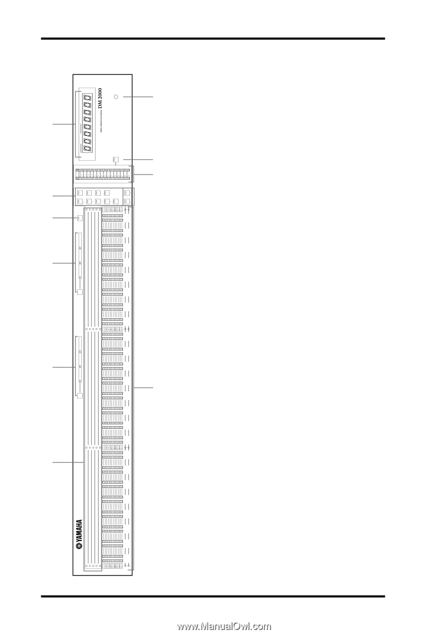
334 Appendix D: Options Meter Bridge Controls LAMP DIMMER A Channel indicators J These indicators show which channels are currently being F CLOCK metered: Input Channels 1-24, 25-48, 49-72, 73-96, or the Out- S BEAT M put Channels (Bus Outs 1-8, Aux Sends 1-12, Matrix Sends 1-4). 6 B INPUT METERING POSITION button & indicators TIME CODE MEASURE H CONTROL ROOM This button is used to set the metering position for Input Channels to pre-EQ, pre-fader, or post-fader. It works in unison with the 9 PRE EQ, PRE FADER, and POST FADER buttons for Input 72 L STEREO R 56 OVER 0 2 4 6 8 10 12 14 18 24 30 36 42 48 8 Channels on the Meter pages. The indicators show the current set- ting. 1 24 REMOTE 1 25 48 REMOTE 2 49 72 REMOTE 3 73 96 REMOTE 4 MASTER 1 48 49 96 5 C OUTPUT METERING POSITION button & indicators This button is used to set the metering position for Output Chan- PEAK HOLD 24 48 72 96 MATRIX 4 OVER 0 3 6 9 12 15 18 24 30 36 48 4 47 48 95 96 nels to pre-EQ, pre-fader, or post-fader. It works in unison with the PRE EQ, PRE FADER, and POST FADER buttons for Output 93 94 45 46 23 47 71 95 MATRIX 3 Channels on the Meter pages. The indicators show the current set- ting. 91 92 43 44 22 46 70 94 MATRIX 2 PRE FADER POST FADER D PEAK HOLD button 89 90 41 42 21 45 69 93 MATRIX 1 3 This button is used to turn the Peak Hold function on and off. Its PRE EQ 87 88 39 40 20 44 68 92 AUX 12 indicator lights up when Peak Hold is on. It works in unison with the PEAK HOLD buttons on the Meter pages. 85 86 37 38 19 43 67 91 AUX 11 83 84 35 36 18 42 66 90 AUX 10 OUTPUT METERING POSITION E LAYER buttons These button are used to select Layers for metering. The button indicator for the currently selected Layer lights up. The [1-24], 81 82 33 34 17 41 65 89 AUX 9 [25-48], [49-72], and [73-96] buttons select the Input Layers. OVER 0 3 6 9 12 15 18 24 30 36 48 79 80 31 32 16 40 64 88 AUX 8 The [MASTER] button selects the Master Layer. The REMOTE 77 78 29 30 15 39 63 87 AUX 7 PRE FADER POST FADER [1-4] buttons select the Remote Layers. If the Meter Follow Layer preference is on (see page 235), these Layers are selected automat- 2 14 38 62 86 AUX 6 27 28 75 76 ically when the LAYER buttons on the DM2000 are pressed. PRE EQ The [1-48] button selects Input Channels 1-48, and the [49-96] 73 74 25 26 13 37 61 85 AUX 5 7 button selects Input Channels 49-96, allowing you to meter up to 48 channels simultaneously. 71 72 23 24 12 36 60 84 AUX 4 69 70 21 22 11 35 59 83 AUX 3 INPUT METERING POSITION F TIMECODE counter This counter displays the current timecode position. When the Pro Tools Remote Layer is selected, it displays the Pro Tools timecode. 67 68 19 20 10 34 58 82 AUX 2 65 66 17 18 9 33 57 81 AUX 1 G Meters OVER 0 3 6 9 12 15 18 24 30 36 48 63 64 15 16 These 12-segment LED meters display the signals levels of the 8 32 56 80 BUS 8 1 channels on the currently selected Layer. 61 62 13 14 7 31 55 79 BUS 7 59 60 11 12 6 30 54 78 BUS 6 H STEREO meters These 32-segment meters display the signal levels of the Stereo Out. 57 58 9 10 5 29 53 77 BUS 5 55 56 78 4 28 52 76 BUS 4 I CONTROL ROOM button This button is used to display the level of the Control Room signal on the STEREO meters. Its indicator lights up when the STEREO meters are displaying Control Room levels. 53 54 56 3 27 51 75 BUS 3 51 52 34 2 26 50 74 BUS 2 49 50 12 1 25 49 73 BUS 1 OVER 0 3 6 9 12 15 18 24 30 36 48 J LAMP DIMMER knob This knob is used to adjust the brightness of the optional LA1800 Light Goosenecks. DM2000-Owner's Manual
-
 1
1 -
2
-
3
-
4
-
5
-
6
-
7
-
8
-
9
-
10
-
11
-
12
-
13
-
14
-
15
-
16
-
17
-
18
-
19
-
20
-
21
-
22
-
23
-
24
-
25
-
26
-
27
-
28
-
29
-
30
-
31
-
32
-
33
-
34
-
35
-
36
-
37
-
38
-
39
-
40
-
41
-
42
-
43
-
44
-
45
-
46
-
47
-
48
-
49
-
50
-
51
-
52
-
53
-
54
-
55
-
56
-
57
-
58
-
59
-
60
-
61
-
62
-
63
-
64
-
65
-
66
-
67
-
68
-
69
-
70
-
71
-
72
-
73
-
74
-
75
-
76
-
77
-
78
-
79
-
80
-
81
-
82
-
83
-
84
-
85
-
86
-
87
-
88
-
89
-
90
-
91
-
92
-
93
-
94
-
95
-
96
-
97
-
98
-
99
-
100
-
101
-
102
-
103
-
104
-
105
-
106
-
107
-
108
-
109
-
110
-
111
-
112
-
113
-
114
-
115
-
116
-
117
-
118
-
119
-
120
-
121
-
122
-
123
-
124
-
125
-
126
-
127
-
128
-
129
-
130
-
131
-
132
-
133
-
134
-
135
-
136
-
137
-
138
-
139
-
140
-
141
-
142
-
143
-
144
-
145
-
146
-
147
-
148
-
149
-
150
-
151
-
152
-
153
-
154
-
155
-
156
-
157
-
158
-
159
-
160
-
161
-
162
-
163
-
164
-
165
-
166
-
167
-
168
-
169
-
170
-
171
-
172
-
173
-
174
-
175
-
176
-
177
-
178
-
179
-
180
-
181
-
182
-
183
-
184
-
185
-
186
-
187
-
188
-
189
-
190
-
191
-
192
-
193
-
194
-
195
-
196
-
197
-
198
-
199
-
200
-
201
-
202
-
203
-
204
-
205
-
206
-
207
-
208
-
209
-
210
-
211
-
212
-
213
-
214
-
215
-
216
-
217
-
218
-
219
-
220
-
221
-
222
-
223
-
224
-
225
-
226
-
227
-
228
-
229
-
230
-
231
-
232
-
233
-
234
-
235
-
236
-
237
-
238
-
239
-
240
-
241
-
242
-
243
-
244
-
245
-
246
-
247
-
248
-
249
-
250
-
251
-
252
-
253
-
254
-
255
-
256
-
257
-
258
-
259
-
260
-
261
-
262
-
263
-
264
-
265
-
266
-
267
-
268
-
269
-
270
-
271
-
272
-
273
-
274
-
275
-
276
-
277
-
278
-
279
-
280
-
281
-
282
-
283
-
284
-
285
-
286
-
287
-
288
-
289
-
290
-
291
-
292
-
293
-
294
-
295
-
296
-
297
-
298
-
299
-
300
-
301
-
302
-
303
-
304
-
305
-
306
-
307
-
308
-
309
-
310
-
311
-
312
-
313
-
314
-
315
-
316
-
317
-
318
-
319
-
320
-
321
-
322
-
323
-
324
-
325
-
326
-
327
-
328
-
329
-
330
-
331
-
332
-
333
-
334
-
335
-
336
-
337
-
338
-
339
-
340
-
341
-
342
-
 343
343 -
 344
344 -
 345
345 -
 346
346 -
 347
347 -
 348
348 -
 349
349 -
 350
350 -
 351
351 -
 352
352 -
 353
353 -
354
-
355
-
356
-
357
-
358
-
359
-
360
-
361
-
362
 |
 |