Yamaha DM2000 Owner's Manual - Page 148
Surround Monitoring, Use the MONITOR [DISPLAY] button to locate the Surround Monitor
 |
View all Yamaha DM2000 manuals
Add to My Manuals
Save this manual to your list of manuals |
Page 148 highlights
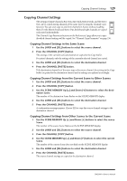
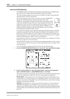
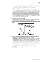
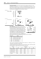
134 Chapter 13-Monitoring & Talkback Surround Monitoring The DM2000 features comprehensive surround monitoring functions, including a pink noise generator for speaker setup, Bass Management, and down mixing. The Surround pages explained in this section are available only when a Surround mode other than Stereo is selected (see page 78). The Surround Monitor signal source is selected by using the SURROUND buttons. The [BUS] button selects the Bus Outs as the source. The [ASSIGN 1] and [ASSIGN 2] buttons select the Inputs of the Slots specified on the Surround Monitor page as the source. Surround mixes from up to six multitrack recorders can be monitored by patching Slot Inputs to Surround Monitor Channels (see page 137) and selecting with the [ASSIGN 1] and [ASSIGN 2] buttons. The level of the Surround Monitor can be set by using the SURROUND MONITOR LEVEL control. SURROUND BUS ASSIGN 1 ASSIGN 2 SURROUND MONITOR LEVEL Surround monitor speakers can be aligned by using the individual Attenuator and Delay parameters on each Surround Monitor Channel. In addition to the standard Ls and Rs speakers, the DM2000 supports Ls2 and Rs2 speakers, with independent Attenuator and Delay parameters, for a more diffused surround monitoring environment. See "Configuring Surround Monitoring" on page 135 for more information. Surround Monitor Channels can be patched to Slot Outputs or Omni Outputs. See "Output Patching" on page 63 for more information. Surround Monitor settings can be stored in the Surround Monitor library, which contains 1 preset memory and 32 user memories. See "Surround Monitor Library" on page 147 for more information. General surround monitoring is performed on the Surround Monitor page. 1 Use the MONITOR [DISPLAY] button to locate the Surround Monitor page. 2 Use the cursor buttons to select the parameters, and use the Parameter wheel, INC/DEC buttons, and [ENTER] button to set them. The number of speaker icons and meters shown on the Surround Monitor page depends on the currently selected Surround mode. The meters indicate Bus Out signal levels. MUTE/SOLO: These parameters are used to mute and solo Surround Channels. A Surround Channel is on when its speaker icon is highlighted. Speaker icons can be selected by using the cursor buttons. When SOLO is on, Surround Channels can be soloed by selecting speaker icons and pressing [ENTER]. SETTING: These buttons are used to select which Slot's Inputs are monitored when the SURROUND [ASSIGN 1] and [ASSIGN 2] buttons are pressed. Up to six Slots can be assigned to each ASSIGN button, in which case the signals are mixed. Individual Slot Inputs can be patched to Surround Monitor Channels on the Surround Monitor Patch page (see page 137). DM2000-Owner's Manual
-
 1
1 -
2
-
3
-
4
-
5
-
6
-
7
-
8
-
9
-
10
-
11
-
12
-
13
-
14
-
15
-
16
-
17
-
18
-
19
-
20
-
21
-
22
-
23
-
24
-
25
-
26
-
27
-
28
-
29
-
30
-
31
-
32
-
33
-
34
-
35
-
36
-
37
-
38
-
39
-
40
-
41
-
42
-
43
-
44
-
45
-
46
-
47
-
48
-
49
-
50
-
51
-
52
-
53
-
54
-
55
-
56
-
57
-
58
-
59
-
60
-
61
-
62
-
63
-
64
-
65
-
66
-
67
-
68
-
69
-
70
-
71
-
72
-
73
-
74
-
75
-
76
-
77
-
78
-
79
-
80
-
81
-
82
-
83
-
84
-
85
-
86
-
87
-
88
-
89
-
90
-
91
-
92
-
93
-
94
-
95
-
96
-
97
-
98
-
99
-
100
-
101
-
102
-
103
-
104
-
105
-
106
-
107
-
108
-
109
-
110
-
111
-
112
-
113
-
114
-
115
-
116
-
117
-
118
-
119
-
120
-
121
-
122
-
123
-
124
-
125
-
126
-
127
-
128
-
129
-
130
-
131
-
132
-
133
-
134
-
135
-
136
-
137
-
138
-
139
-
140
-
141
-
142
-
 143
143 -
 144
144 -
 145
145 -
 146
146 -
 147
147 -
 148
148 -
 149
149 -
 150
150 -
 151
151 -
 152
152 -
 153
153 -
154
-
155
-
156
-
157
-
158
-
159
-
160
-
161
-
162
-
163
-
164
-
165
-
166
-
167
-
168
-
169
-
170
-
171
-
172
-
173
-
174
-
175
-
176
-
177
-
178
-
179
-
180
-
181
-
182
-
183
-
184
-
185
-
186
-
187
-
188
-
189
-
190
-
191
-
192
-
193
-
194
-
195
-
196
-
197
-
198
-
199
-
200
-
201
-
202
-
203
-
204
-
205
-
206
-
207
-
208
-
209
-
210
-
211
-
212
-
213
-
214
-
215
-
216
-
217
-
218
-
219
-
220
-
221
-
222
-
223
-
224
-
225
-
226
-
227
-
228
-
229
-
230
-
231
-
232
-
233
-
234
-
235
-
236
-
237
-
238
-
239
-
240
-
241
-
242
-
243
-
244
-
245
-
246
-
247
-
248
-
249
-
250
-
251
-
252
-
253
-
254
-
255
-
256
-
257
-
258
-
259
-
260
-
261
-
262
-
263
-
264
-
265
-
266
-
267
-
268
-
269
-
270
-
271
-
272
-
273
-
274
-
275
-
276
-
277
-
278
-
279
-
280
-
281
-
282
-
283
-
284
-
285
-
286
-
287
-
288
-
289
-
290
-
291
-
292
-
293
-
294
-
295
-
296
-
297
-
298
-
299
-
300
-
301
-
302
-
303
-
304
-
305
-
306
-
307
-
308
-
309
-
310
-
311
-
312
-
313
-
314
-
315
-
316
-
317
-
318
-
319
-
320
-
321
-
322
-
323
-
324
-
325
-
326
-
327
-
328
-
329
-
330
-
331
-
332
-
333
-
334
-
335
-
336
-
337
-
338
-
339
-
340
-
341
-
342
-
343
-
344
-
345
-
346
-
347
-
348
-
349
-
350
-
351
-
352
-
353
-
354
-
355
-
356
-
357
-
358
-
359
-
360
-
361
-
362
 |
 |