Yamaha DM2000 Owner's Manual - Page 40
Monitor
 |
View all Yamaha DM2000 manuals
Add to My Manuals
Save this manual to your list of manuals |
Page 40 highlights
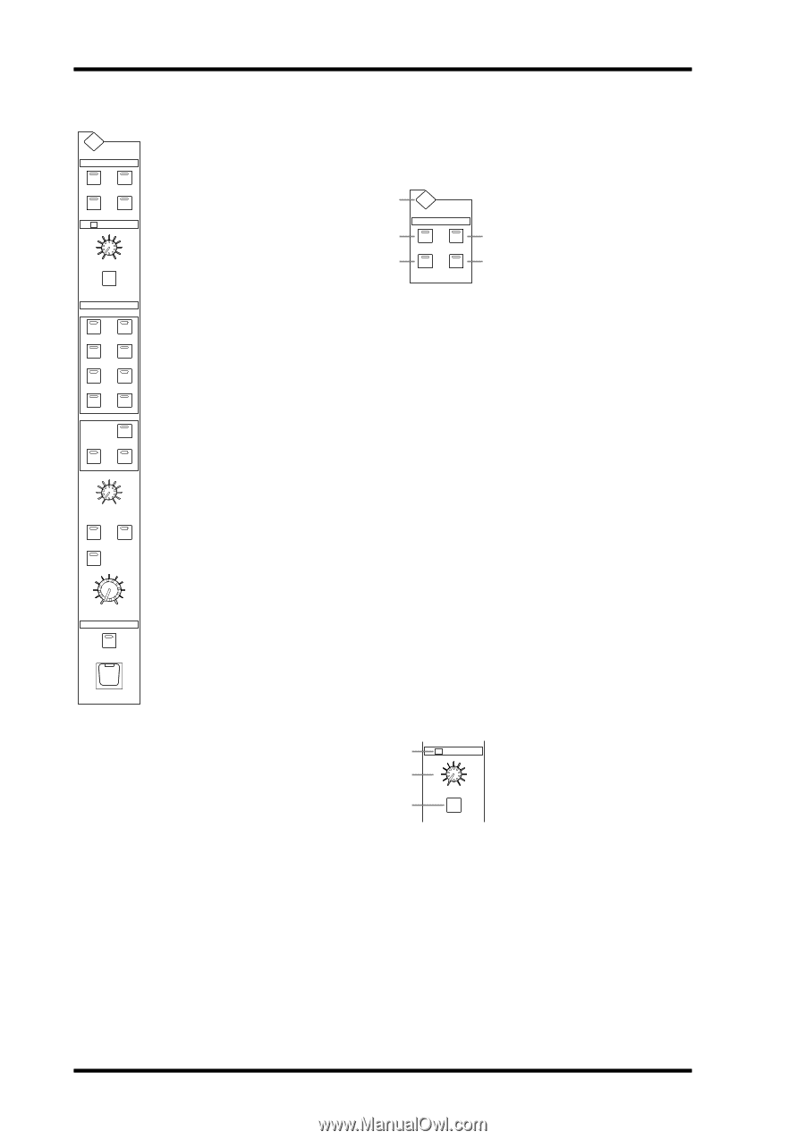
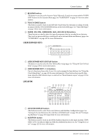
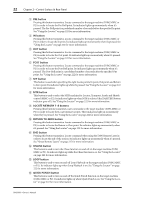
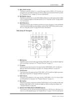
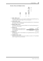
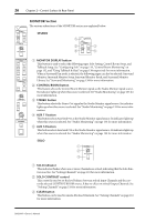
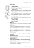
26 Chapter 2-Control Surface & Rear Panel MONITOR Section MONITOR The various subsections of the MONITOR section are explained below. DISPLAY STUDIO CONTROL STEREO ROOM AUX 11 AUX 12 SOLO SOLO CONTRAST STUDIO 1 2 4 MONITOR DISPLAY STUDIO CONTROL STEREO ROOM AUX 11 AUX 12 3 5 CLEAR CONTROL ROOM STEREO 2TR D1 2TR A1 2TR D2 2TR A2 2TR D3 STEREO ASSIGN 1 ASSIGN 2 SURROUND BUS ASSIGN 1 ASSIGN 2 A MONITOR DISPLAY button This button is used to select the following pages: Solo Setting, Control Room Setup, and Talkback Setup. See "Configuring Solo" on page 119, "Control Room Monitoring" on page 132, and "Using Talkback & Slate" on page 138 respectively for more information. When a Surround Pan mode is selected, the following pages can also be selected: Surround Monitor, Surround Monitor Setup, Surround Monitor Patch, and Surround Monitor Library. See "Surround Monitoring" on page 134 for more information. B CONTROL ROOM button This button selects the Control Room Monitor signal as the Studio Monitor signal source. Its indicator lights up when this source is selected. See "Studio Monitoring" on page 133 for more information. SURROUND MONITOR LEVEL MONO DIMMER SMALL C STEREO button This button selects the Stereo Out signal as the Studio Monitor signal source. Its indicator lights up when this source is selected. See "Studio Monitoring" on page 133 for more information. 0 10 CONTROL ROOM LEVEL TALKBACK D AUX 11 button This button selects Aux Send #11 as the Studio Monitor signal source. Its indicator lights up when this source is selected. See "Studio Monitoring" on page 133 for more information. SLATE E AUX 12 button This button selects Aux Send #12 as the Studio Monitor signal source. Its indicator lights up when this source is selected. See "Studio Monitoring" on page 133 for more information. TALKBACK SOLO 1 2 3 SOLO SOLO CONTRAST CLEAR A SOLO indicator This indicator flashes when one or more Channels are soloed, indicating that the Solo function is active. See "Soloing Channels" on page 118 for more information. B SOLO CONTRAST control This control is used to set the level balance between soloed Input Channels and the currently selected CONTROL ROOM source. It has no effect on soloed Output Channels. See "Soloing Channels" on page 118 for more information. C CLEAR button This button can be used to unsolo all soloed Channels. See "Soloing Channels" on page 118 for more information. DM2000-Owner's Manual
-
 1
1 -
2
-
3
-
4
-
5
-
6
-
7
-
8
-
9
-
10
-
11
-
12
-
13
-
14
-
15
-
16
-
17
-
18
-
19
-
20
-
21
-
22
-
23
-
24
-
25
-
26
-
27
-
28
-
29
-
30
-
31
-
32
-
33
-
34
-
 35
35 -
 36
36 -
 37
37 -
 38
38 -
 39
39 -
 40
40 -
 41
41 -
 42
42 -
 43
43 -
 44
44 -
 45
45 -
46
-
47
-
48
-
49
-
50
-
51
-
52
-
53
-
54
-
55
-
56
-
57
-
58
-
59
-
60
-
61
-
62
-
63
-
64
-
65
-
66
-
67
-
68
-
69
-
70
-
71
-
72
-
73
-
74
-
75
-
76
-
77
-
78
-
79
-
80
-
81
-
82
-
83
-
84
-
85
-
86
-
87
-
88
-
89
-
90
-
91
-
92
-
93
-
94
-
95
-
96
-
97
-
98
-
99
-
100
-
101
-
102
-
103
-
104
-
105
-
106
-
107
-
108
-
109
-
110
-
111
-
112
-
113
-
114
-
115
-
116
-
117
-
118
-
119
-
120
-
121
-
122
-
123
-
124
-
125
-
126
-
127
-
128
-
129
-
130
-
131
-
132
-
133
-
134
-
135
-
136
-
137
-
138
-
139
-
140
-
141
-
142
-
143
-
144
-
145
-
146
-
147
-
148
-
149
-
150
-
151
-
152
-
153
-
154
-
155
-
156
-
157
-
158
-
159
-
160
-
161
-
162
-
163
-
164
-
165
-
166
-
167
-
168
-
169
-
170
-
171
-
172
-
173
-
174
-
175
-
176
-
177
-
178
-
179
-
180
-
181
-
182
-
183
-
184
-
185
-
186
-
187
-
188
-
189
-
190
-
191
-
192
-
193
-
194
-
195
-
196
-
197
-
198
-
199
-
200
-
201
-
202
-
203
-
204
-
205
-
206
-
207
-
208
-
209
-
210
-
211
-
212
-
213
-
214
-
215
-
216
-
217
-
218
-
219
-
220
-
221
-
222
-
223
-
224
-
225
-
226
-
227
-
228
-
229
-
230
-
231
-
232
-
233
-
234
-
235
-
236
-
237
-
238
-
239
-
240
-
241
-
242
-
243
-
244
-
245
-
246
-
247
-
248
-
249
-
250
-
251
-
252
-
253
-
254
-
255
-
256
-
257
-
258
-
259
-
260
-
261
-
262
-
263
-
264
-
265
-
266
-
267
-
268
-
269
-
270
-
271
-
272
-
273
-
274
-
275
-
276
-
277
-
278
-
279
-
280
-
281
-
282
-
283
-
284
-
285
-
286
-
287
-
288
-
289
-
290
-
291
-
292
-
293
-
294
-
295
-
296
-
297
-
298
-
299
-
300
-
301
-
302
-
303
-
304
-
305
-
306
-
307
-
308
-
309
-
310
-
311
-
312
-
313
-
314
-
315
-
316
-
317
-
318
-
319
-
320
-
321
-
322
-
323
-
324
-
325
-
326
-
327
-
328
-
329
-
330
-
331
-
332
-
333
-
334
-
335
-
336
-
337
-
338
-
339
-
340
-
341
-
342
-
343
-
344
-
345
-
346
-
347
-
348
-
349
-
350
-
351
-
352
-
353
-
354
-
355
-
356
-
357
-
358
-
359
-
360
-
361
-
362
 |
 |