Yamaha DM2000 Owner's Manual - Page 33
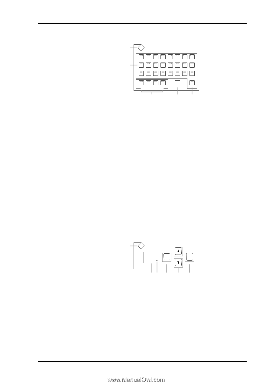
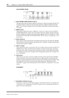
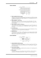
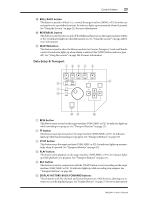
ATRACK ARMING DISPLAY button BTRACK ARMING 1-24 buttons CTRACK ARMING GROUP A-D buttons DALL CLEAR button EMASTER button ASCENE MEMORY DISPLAY button BScene memory display CEdit indicator
 |
View all Yamaha DM2000 manuals
Add to My Manuals
Save this manual to your list of manuals |
Page 33 highlights
Control Surface 19 TRACK ARMING 1 2 TRACK ARMING DISPLAY 1 2 3 4 5 6 7 8 9 10 11 12 13 14 15 16 17 18 19 20 21 22 23 24 A B C D TRACK ARMING GROUP 3 ALL CLEAR MASTER 45 A TRACK ARMING DISPLAY button This button is used to select the following pages: Track Arming Group, MTR Track Arming Configuration, and Master Track Arming Configuration. See "Arming Machine Tracks" on page 225 for more information. B TRACK ARMING 1-24 buttons These buttons are used to arm tracks on the target machine (DAW, MMC or P2). Their indicators light up when tracks are armed. See "Arming Machine Tracks" on page 225 for more information. C TRACK ARMING GROUP A-D buttons These buttons are used to select the track arming groups A, B, C, and D. The indicator for the currently selected group lights up. See "Arming Machine Tracks" on page 225 for more information. D ALL CLEAR button This button is used to clear all track arming on the target machine (DAW, MMC or P2). See "Arming Machine Tracks" on page 225 for more information. E MASTER button This button is used to select Master or MTR machines for track arming. Its indicator lights up when Master is selected, and is off when MTR is selected. See "About Machine Control (MMC & P2)" on page 220 for more information. SCENE MEMORY 1 SCENE MEMORY DISPLAY 00 STORE RECALL 23 4 5 6 A SCENE MEMORY DISPLAY button This button is used to select the following pages: Scene Memory, Input Channel Fade Time, Output Fade Time, Recall Safe, and Scene Memory Sort. See "Scene Memories" on page 157 for more information. B Scene memory display This displays the number of the currently selected Scene memory. See "Scene Memories" on page 157 for more information. C Edit indicator This indicates that the current mix settings no longer match those of the Scene that was recalled last. See "Edit Buffer & Edit Indicator" on page 157 for more information. DM2000-Owner's Manual
-
 1
1 -
2
-
3
-
4
-
5
-
6
-
7
-
8
-
9
-
10
-
11
-
12
-
13
-
14
-
15
-
16
-
17
-
18
-
19
-
20
-
21
-
22
-
23
-
24
-
25
-
26
-
27
-
 28
28 -
 29
29 -
 30
30 -
 31
31 -
 32
32 -
 33
33 -
 34
34 -
 35
35 -
 36
36 -
 37
37 -
 38
38 -
39
-
40
-
41
-
42
-
43
-
44
-
45
-
46
-
47
-
48
-
49
-
50
-
51
-
52
-
53
-
54
-
55
-
56
-
57
-
58
-
59
-
60
-
61
-
62
-
63
-
64
-
65
-
66
-
67
-
68
-
69
-
70
-
71
-
72
-
73
-
74
-
75
-
76
-
77
-
78
-
79
-
80
-
81
-
82
-
83
-
84
-
85
-
86
-
87
-
88
-
89
-
90
-
91
-
92
-
93
-
94
-
95
-
96
-
97
-
98
-
99
-
100
-
101
-
102
-
103
-
104
-
105
-
106
-
107
-
108
-
109
-
110
-
111
-
112
-
113
-
114
-
115
-
116
-
117
-
118
-
119
-
120
-
121
-
122
-
123
-
124
-
125
-
126
-
127
-
128
-
129
-
130
-
131
-
132
-
133
-
134
-
135
-
136
-
137
-
138
-
139
-
140
-
141
-
142
-
143
-
144
-
145
-
146
-
147
-
148
-
149
-
150
-
151
-
152
-
153
-
154
-
155
-
156
-
157
-
158
-
159
-
160
-
161
-
162
-
163
-
164
-
165
-
166
-
167
-
168
-
169
-
170
-
171
-
172
-
173
-
174
-
175
-
176
-
177
-
178
-
179
-
180
-
181
-
182
-
183
-
184
-
185
-
186
-
187
-
188
-
189
-
190
-
191
-
192
-
193
-
194
-
195
-
196
-
197
-
198
-
199
-
200
-
201
-
202
-
203
-
204
-
205
-
206
-
207
-
208
-
209
-
210
-
211
-
212
-
213
-
214
-
215
-
216
-
217
-
218
-
219
-
220
-
221
-
222
-
223
-
224
-
225
-
226
-
227
-
228
-
229
-
230
-
231
-
232
-
233
-
234
-
235
-
236
-
237
-
238
-
239
-
240
-
241
-
242
-
243
-
244
-
245
-
246
-
247
-
248
-
249
-
250
-
251
-
252
-
253
-
254
-
255
-
256
-
257
-
258
-
259
-
260
-
261
-
262
-
263
-
264
-
265
-
266
-
267
-
268
-
269
-
270
-
271
-
272
-
273
-
274
-
275
-
276
-
277
-
278
-
279
-
280
-
281
-
282
-
283
-
284
-
285
-
286
-
287
-
288
-
289
-
290
-
291
-
292
-
293
-
294
-
295
-
296
-
297
-
298
-
299
-
300
-
301
-
302
-
303
-
304
-
305
-
306
-
307
-
308
-
309
-
310
-
311
-
312
-
313
-
314
-
315
-
316
-
317
-
318
-
319
-
320
-
321
-
322
-
323
-
324
-
325
-
326
-
327
-
328
-
329
-
330
-
331
-
332
-
333
-
334
-
335
-
336
-
337
-
338
-
339
-
340
-
341
-
342
-
343
-
344
-
345
-
346
-
347
-
348
-
349
-
350
-
351
-
352
-
353
-
354
-
355
-
356
-
357
-
358
-
359
-
360
-
361
-
362
 |
 |