Yamaha DM2000 Owner's Manual - Page 300
REVERB 5.1, OCTA REVERB, One input, six output reverb for 5.1 surround, with surround panning.
 |
View all Yamaha DM2000 manuals
Add to My Manuals
Save this manual to your list of manuals |
Page 300 highlights
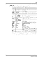
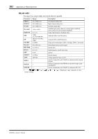
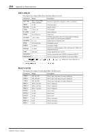
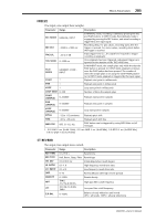
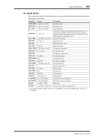
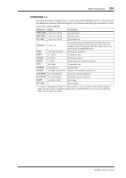
286 Appendix A: Parameter Lists REVERB 5.1 One input, six output reverb for 5.1 surround, with surround panning. Parameter Range Description REV TIME REV TYPE HI. RATIO DIFF. DENSITY HPF LPF DIV. ROOMSIZE POS L/R POS F/R POS CTRL ER L/R ER F/R ER LVL ER CTRL REV L/R REV F/R REV LVL REV CTRL 0.3-99.0 s Hall, Room, Stage, Plate 0.1-1.0 0-10 0-100% THRU, 21.2 Hz-8.00 kHz 50.0 Hz-16.0 kHz, THRU 0-100% 0.1-20.0 L63-R63 F63-R63 OFF, NOR, INV L63-R63 F63-R63 0-100% OFF, NOR, INV L63-R63 F63-R63 0-100% OFF, NOR, INV Reverb time Reverb type High-frequency reverb time ratio Reverb diffusion (left-right reverb spread) Reverb density High-pass filter cutoff frequency Low-pass filter cutoff frequency Divergence determines how the front center signal is fed to the Left, Right, and Center channels. When set to 0%, it's fed only to the Left and Right channels (i.e., Phantom Center). When set to 50%, it's fed equally to the Left, Right, and Center channels. When set to 100%, it's fed to only the Center channel (i.e., Real Center). Size of simulated room's reverb Left/right listening position Front/rear listening position 1 Left/right early reflections position Front/rear early reflections position Early reflections level 1 Left/right reverb position Front/rear reverb position Reverb level 1 1. When set to NOR, the position can be set by using the Joystick so long as the SELECTED CHANNEL PAN/SURROUND [EFFECT] button's indicator is on. When set to INV, the Joystick will work inversely. When set to OFF, Joystick control is off. OCTA REVERB Eight input, eight output reverb. Parameter Range Description REV TIME REV TYPE INI. DLY HI. RATIO LO. RATIO DIFF. DENSITY HPF LPF E/R BAL. 0.3-99.0 s Reverb time Hall, Room, Stage, Plate Reverb type 0.0-100.0 ms Initial delay before reverb begins 0.1-1.0 High-frequency reverb time ratio 0.1-2.4 Low-frequency reverb time ratio 0-10 Reverb diffusion (left-right reverb spread) 0-100% Reverb density THRU, 21.2 Hz-8.00 kHz 50.0 Hz-16.0 kHz, THRU 0-100% High-pass filter cutoff frequency Low-pass filter cutoff frequency Balance of early reflections and reverb (0% = all reverb, 100% = all early reflections) DM2000-Owner's Manual
-
 1
1 -
2
-
3
-
4
-
5
-
6
-
7
-
8
-
9
-
10
-
11
-
12
-
13
-
14
-
15
-
16
-
17
-
18
-
19
-
20
-
21
-
22
-
23
-
24
-
25
-
26
-
27
-
28
-
29
-
30
-
31
-
32
-
33
-
34
-
35
-
36
-
37
-
38
-
39
-
40
-
41
-
42
-
43
-
44
-
45
-
46
-
47
-
48
-
49
-
50
-
51
-
52
-
53
-
54
-
55
-
56
-
57
-
58
-
59
-
60
-
61
-
62
-
63
-
64
-
65
-
66
-
67
-
68
-
69
-
70
-
71
-
72
-
73
-
74
-
75
-
76
-
77
-
78
-
79
-
80
-
81
-
82
-
83
-
84
-
85
-
86
-
87
-
88
-
89
-
90
-
91
-
92
-
93
-
94
-
95
-
96
-
97
-
98
-
99
-
100
-
101
-
102
-
103
-
104
-
105
-
106
-
107
-
108
-
109
-
110
-
111
-
112
-
113
-
114
-
115
-
116
-
117
-
118
-
119
-
120
-
121
-
122
-
123
-
124
-
125
-
126
-
127
-
128
-
129
-
130
-
131
-
132
-
133
-
134
-
135
-
136
-
137
-
138
-
139
-
140
-
141
-
142
-
143
-
144
-
145
-
146
-
147
-
148
-
149
-
150
-
151
-
152
-
153
-
154
-
155
-
156
-
157
-
158
-
159
-
160
-
161
-
162
-
163
-
164
-
165
-
166
-
167
-
168
-
169
-
170
-
171
-
172
-
173
-
174
-
175
-
176
-
177
-
178
-
179
-
180
-
181
-
182
-
183
-
184
-
185
-
186
-
187
-
188
-
189
-
190
-
191
-
192
-
193
-
194
-
195
-
196
-
197
-
198
-
199
-
200
-
201
-
202
-
203
-
204
-
205
-
206
-
207
-
208
-
209
-
210
-
211
-
212
-
213
-
214
-
215
-
216
-
217
-
218
-
219
-
220
-
221
-
222
-
223
-
224
-
225
-
226
-
227
-
228
-
229
-
230
-
231
-
232
-
233
-
234
-
235
-
236
-
237
-
238
-
239
-
240
-
241
-
242
-
243
-
244
-
245
-
246
-
247
-
248
-
249
-
250
-
251
-
252
-
253
-
254
-
255
-
256
-
257
-
258
-
259
-
260
-
261
-
262
-
263
-
264
-
265
-
266
-
267
-
268
-
269
-
270
-
271
-
272
-
273
-
274
-
275
-
276
-
277
-
278
-
279
-
280
-
281
-
282
-
283
-
284
-
285
-
286
-
287
-
288
-
289
-
290
-
291
-
292
-
293
-
294
-
 295
295 -
 296
296 -
 297
297 -
 298
298 -
 299
299 -
 300
300 -
 301
301 -
 302
302 -
 303
303 -
 304
304 -
 305
305 -
306
-
307
-
308
-
309
-
310
-
311
-
312
-
313
-
314
-
315
-
316
-
317
-
318
-
319
-
320
-
321
-
322
-
323
-
324
-
325
-
326
-
327
-
328
-
329
-
330
-
331
-
332
-
333
-
334
-
335
-
336
-
337
-
338
-
339
-
340
-
341
-
342
-
343
-
344
-
345
-
346
-
347
-
348
-
349
-
350
-
351
-
352
-
353
-
354
-
355
-
356
-
357
-
358
-
359
-
360
-
361
-
362
 |
 |