Yamaha DM2000 Owner's Manual - Page 27
Phase/insert, Delay, Phase/insert Display Button
 |
View all Yamaha DM2000 manuals
Add to My Manuals
Save this manual to your list of manuals |
Page 27 highlights
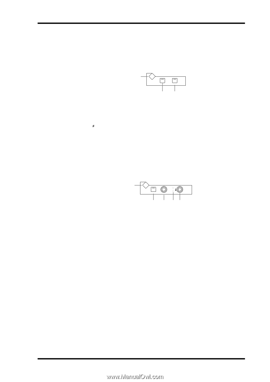
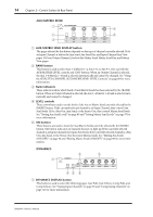
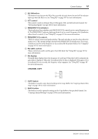
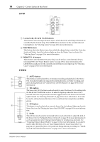
Control Surface 13 E ROUTING 1-8 buttons These buttons are used to route the currently selected Input Channel to the Bus Outs. The button indicators of Bus Outs to which the Input Channel is routed light up. See "Routing Input Channels" on page 75 for more information. PHASE/INSERT 1 PHASE / INSERT DISPLAY INSERT ON 23 A PHASE/INSERT DISPLAY button This button is used to select the Input Channel Phase and Insert pages. See "Reversing the Signal Phase" on page 68 and "Using Inserts" on page 111 for more information. B Phase [ ] button This button is used to reverse the signal phase of the currently selected Input Channel. Its indicator lights up when the phase is reversed. See "Reversing the Signal Phase" on page 68 for more information. C INSERT ON button This button is used to turn on and off the Insert of the currently selected channel. Its indicator lights up when the Insert is on. See "Using Inserts" on page 111 for more information. DELAY 1 DELAY DISPLAY ON FB MIX TIME 2 3 45 A DELAY DISPLAY button This button is used to select the Delay pages. See "Delaying Channel Signals" on page 117 for more information. B ON button This button is used to turn on and off the Delay of the currently selected channel. Its indicator lights up when the Delay function is on. See "Delaying Channel Signals" on page 117 for more information. C TIME control This control is used to set the delay time of the currently selected channel's Delay function. See "Delaying Channel Signals" on page 117 for more information. D FB/MIX indicators These indicators show whether the FB/MIX control is set to control Feedback Gain or Feedback Mix. The FB indicator lights up when it's set to control Feedback Gain; the MIX indicator, when its set to control Feedback Mix. See "Delaying Channel Signals" on page 117 for more information. E FB/MIX control This is a rotary control and push switch. When the currently selected channel is an Input Channel, the push switch can be used to select either Feedback Gain (FB) or Feedback Mix (MIX). The rotary control is used to set the Feedback Gain or Feedback Mix, as selected by the push switch. See "Delaying Channel Signals" on page 117 for more information. DM2000-Owner's Manual
-
 1
1 -
2
-
3
-
4
-
5
-
6
-
7
-
8
-
9
-
10
-
11
-
12
-
13
-
14
-
15
-
16
-
17
-
18
-
19
-
20
-
21
-
 22
22 -
 23
23 -
 24
24 -
 25
25 -
 26
26 -
 27
27 -
 28
28 -
 29
29 -
 30
30 -
 31
31 -
 32
32 -
33
-
34
-
35
-
36
-
37
-
38
-
39
-
40
-
41
-
42
-
43
-
44
-
45
-
46
-
47
-
48
-
49
-
50
-
51
-
52
-
53
-
54
-
55
-
56
-
57
-
58
-
59
-
60
-
61
-
62
-
63
-
64
-
65
-
66
-
67
-
68
-
69
-
70
-
71
-
72
-
73
-
74
-
75
-
76
-
77
-
78
-
79
-
80
-
81
-
82
-
83
-
84
-
85
-
86
-
87
-
88
-
89
-
90
-
91
-
92
-
93
-
94
-
95
-
96
-
97
-
98
-
99
-
100
-
101
-
102
-
103
-
104
-
105
-
106
-
107
-
108
-
109
-
110
-
111
-
112
-
113
-
114
-
115
-
116
-
117
-
118
-
119
-
120
-
121
-
122
-
123
-
124
-
125
-
126
-
127
-
128
-
129
-
130
-
131
-
132
-
133
-
134
-
135
-
136
-
137
-
138
-
139
-
140
-
141
-
142
-
143
-
144
-
145
-
146
-
147
-
148
-
149
-
150
-
151
-
152
-
153
-
154
-
155
-
156
-
157
-
158
-
159
-
160
-
161
-
162
-
163
-
164
-
165
-
166
-
167
-
168
-
169
-
170
-
171
-
172
-
173
-
174
-
175
-
176
-
177
-
178
-
179
-
180
-
181
-
182
-
183
-
184
-
185
-
186
-
187
-
188
-
189
-
190
-
191
-
192
-
193
-
194
-
195
-
196
-
197
-
198
-
199
-
200
-
201
-
202
-
203
-
204
-
205
-
206
-
207
-
208
-
209
-
210
-
211
-
212
-
213
-
214
-
215
-
216
-
217
-
218
-
219
-
220
-
221
-
222
-
223
-
224
-
225
-
226
-
227
-
228
-
229
-
230
-
231
-
232
-
233
-
234
-
235
-
236
-
237
-
238
-
239
-
240
-
241
-
242
-
243
-
244
-
245
-
246
-
247
-
248
-
249
-
250
-
251
-
252
-
253
-
254
-
255
-
256
-
257
-
258
-
259
-
260
-
261
-
262
-
263
-
264
-
265
-
266
-
267
-
268
-
269
-
270
-
271
-
272
-
273
-
274
-
275
-
276
-
277
-
278
-
279
-
280
-
281
-
282
-
283
-
284
-
285
-
286
-
287
-
288
-
289
-
290
-
291
-
292
-
293
-
294
-
295
-
296
-
297
-
298
-
299
-
300
-
301
-
302
-
303
-
304
-
305
-
306
-
307
-
308
-
309
-
310
-
311
-
312
-
313
-
314
-
315
-
316
-
317
-
318
-
319
-
320
-
321
-
322
-
323
-
324
-
325
-
326
-
327
-
328
-
329
-
330
-
331
-
332
-
333
-
334
-
335
-
336
-
337
-
338
-
339
-
340
-
341
-
342
-
343
-
344
-
345
-
346
-
347
-
348
-
349
-
350
-
351
-
352
-
353
-
354
-
355
-
356
-
357
-
358
-
359
-
360
-
361
-
362
 |
 |