Yamaha DM2000 Owner's Manual - Page 20
SmartMedia CARD Slot, MATRIX SELECT
 |
View all Yamaha DM2000 manuals
Add to My Manuals
Save this manual to your list of manuals |
Page 20 highlights
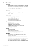
6 Chapter 2-Control Surface & Rear Panel D SOLO buttons These buttons are used to solo Channels. The [SOLO] button indicators of channels that are soloed light up. See "Soloing Channels" on page 118 for more information. E ON buttons These buttons are used to mute Input and Output Channels. Their exact operation depends on the currently selected Layer. The [ON] button indicators of channels that are on light up. F Channel strip displays These fluorescent displays graphically display the value of the Input or Output Channel parameter currently assigned to the Encoders. They also display routing settings, and the on/off status of the EQ, Insert, Delay, Comp, and Gate functions. They also display Long and Short channel names and indicate the currently selected channel. See "Channel Strip Displays" on page 39 for more information. G Channel faders These 100 mm touch-sensitive motorized faders are used to set the levels of Input Channels, Bus Outs, Aux Sends, and Matrix Sends. Their exact operation depends on the currently selected Fader mode and Layer. See "Selecting Fader Modes" on page 44 for more information. Faders can be grouped for simultaneous operation. See "Grouping Input Channel Faders" on page 74 and "Grouping Output Channel Faders" on page 122 for more information. Faders can also be used to select Input and Output Channels. See "Auto Channel Select & Touch Sense Select" on page 44 for more information. They can also be used to punch channels in and out during Automix recording. See "Punching In & Out Individual Parameters" on page 175 for more information. SmartMedia CARD Slot This CARD slot is for use with SmartMedia (3.3 V), which can be used to store DM2000 data, including Setups, Scenes, Automixes, Libraries, and so on. See "Saving DM2000 Data to SmartMedia" on page 231 for more information. MATRIX SELECT 1 MATRIX SELECT DISPLAY MATRIX 1 MATRIX 2 MATRIX 3 MATRIX 4 2 3.3V CARD A MATRIX SELECT DISPLAY button This button is used to select the following pages: Matrix Send, Matrix Send Pan, and Matrix View. See "Matrix Sends" on page 97 for more information. B MATRIX 1-4 buttons These buttons are used to select Matrix Sends when sending Bus Out, Aux Send, and Stereo Out signals to Matrix Sends. The button indicator of the currently selected Matrix Send lights up. See "Matrix Sends" on page 97 for more information. DM2000-Owner's Manual
-
 1
1 -
2
-
3
-
4
-
5
-
6
-
7
-
8
-
9
-
10
-
11
-
12
-
13
-
14
-
 15
15 -
 16
16 -
 17
17 -
 18
18 -
 19
19 -
 20
20 -
 21
21 -
 22
22 -
 23
23 -
 24
24 -
 25
25 -
26
-
27
-
28
-
29
-
30
-
31
-
32
-
33
-
34
-
35
-
36
-
37
-
38
-
39
-
40
-
41
-
42
-
43
-
44
-
45
-
46
-
47
-
48
-
49
-
50
-
51
-
52
-
53
-
54
-
55
-
56
-
57
-
58
-
59
-
60
-
61
-
62
-
63
-
64
-
65
-
66
-
67
-
68
-
69
-
70
-
71
-
72
-
73
-
74
-
75
-
76
-
77
-
78
-
79
-
80
-
81
-
82
-
83
-
84
-
85
-
86
-
87
-
88
-
89
-
90
-
91
-
92
-
93
-
94
-
95
-
96
-
97
-
98
-
99
-
100
-
101
-
102
-
103
-
104
-
105
-
106
-
107
-
108
-
109
-
110
-
111
-
112
-
113
-
114
-
115
-
116
-
117
-
118
-
119
-
120
-
121
-
122
-
123
-
124
-
125
-
126
-
127
-
128
-
129
-
130
-
131
-
132
-
133
-
134
-
135
-
136
-
137
-
138
-
139
-
140
-
141
-
142
-
143
-
144
-
145
-
146
-
147
-
148
-
149
-
150
-
151
-
152
-
153
-
154
-
155
-
156
-
157
-
158
-
159
-
160
-
161
-
162
-
163
-
164
-
165
-
166
-
167
-
168
-
169
-
170
-
171
-
172
-
173
-
174
-
175
-
176
-
177
-
178
-
179
-
180
-
181
-
182
-
183
-
184
-
185
-
186
-
187
-
188
-
189
-
190
-
191
-
192
-
193
-
194
-
195
-
196
-
197
-
198
-
199
-
200
-
201
-
202
-
203
-
204
-
205
-
206
-
207
-
208
-
209
-
210
-
211
-
212
-
213
-
214
-
215
-
216
-
217
-
218
-
219
-
220
-
221
-
222
-
223
-
224
-
225
-
226
-
227
-
228
-
229
-
230
-
231
-
232
-
233
-
234
-
235
-
236
-
237
-
238
-
239
-
240
-
241
-
242
-
243
-
244
-
245
-
246
-
247
-
248
-
249
-
250
-
251
-
252
-
253
-
254
-
255
-
256
-
257
-
258
-
259
-
260
-
261
-
262
-
263
-
264
-
265
-
266
-
267
-
268
-
269
-
270
-
271
-
272
-
273
-
274
-
275
-
276
-
277
-
278
-
279
-
280
-
281
-
282
-
283
-
284
-
285
-
286
-
287
-
288
-
289
-
290
-
291
-
292
-
293
-
294
-
295
-
296
-
297
-
298
-
299
-
300
-
301
-
302
-
303
-
304
-
305
-
306
-
307
-
308
-
309
-
310
-
311
-
312
-
313
-
314
-
315
-
316
-
317
-
318
-
319
-
320
-
321
-
322
-
323
-
324
-
325
-
326
-
327
-
328
-
329
-
330
-
331
-
332
-
333
-
334
-
335
-
336
-
337
-
338
-
339
-
340
-
341
-
342
-
343
-
344
-
345
-
346
-
347
-
348
-
349
-
350
-
351
-
352
-
353
-
354
-
355
-
356
-
357
-
358
-
359
-
360
-
361
-
362
 |
 |