Yamaha DM2000 Owner's Manual - Page 59
Selecting Encoder Modes, Select a Layer, as explained
 |
View all Yamaha DM2000 manuals
Add to My Manuals
Save this manual to your list of manuals |
Page 59 highlights
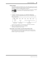
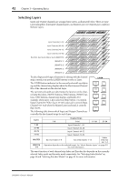
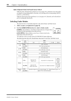
Selecting Encoder Modes 45 Selecting Encoder Modes The exact function of each Encoder depends on the selected Layer and Encoder mode. There are two preset Encoder modes, Pan and Aux/Mtrx, and four assignable modes, for which you can choose from over 40 parameters. 1 Select a Layer, as explained in page 42. 2 Use the ENCODER MODE buttons to select an Encoder mode. ENCODER MODE [PAN]: Encoders function as Pan controls. DISPLAY [AUX/MTRX]: Encoders control Aux or Matrix Send levels, depending on the selected Layer. PAN PAN AUX/ MTRX SEND LEVEL [ASSIGN 1-4]: Encoders control the parameters assigned to the ASSIGN buttons. See "Assigning ASSIGN 1 ASSIGN 2 ASSIGN 3 ASSIGN 4 INPUT OUTPUT SEND ASSIGN INSERT Parameters to the ENCODER MODE Assign Buttons" on page 46 for more information. The indicator of the currently selected ENCODER MODE button lights up. The following table shows the exact Encoder functions for each Layer and Encoder mode. Layer 1-24 25-48 49-72 73-96 Master Remote 1-4 Encoder Mode Pan Aux/Mtrx Assign 1-4 Pan Aux/Mtrx Assign 1-4 Pan Aux/Mtrx Assign 1-4 Pan Aux/Mtrx Assign 1-4 Pan Aux/Mtrx Assign 1-4 Pan Aux/Mtrx Assign 1-4 Encoder 1-8 9-16 17-20 21-24 CH 1-24: pan CH 1-24: Aux Send level CH 1-24: assigned parameter CH 25-48: pan CH 25-48: Aux Send level CH 25-48: assigned parameter CH 49-72: pan CH 49-72: Aux Send level CH 49-72: assigned parameter CH 73-96 pan CH 73-96: Aux Send level CH 73-96: assigned parameter No operation No operation Bus Out 1-8: Matrix Send level Aux Send 1-12: Matrix Send level Bus Out 1-8: assigned parameter Aux Send 1-12: assigned parameter Matrix 1-4: Bal- ance No operation Matrix Send 1-4: assigned parameter Operation depends on the selected target. See "About Remote Layers" on page 217 for more information. The values of the parameters being controlled by the Encoders are displayed graphically by the channel strip displays. See "Channel Strip Displays" on page 39 for more information. DM2000-Owner's Manual
-
 1
1 -
2
-
3
-
4
-
5
-
6
-
7
-
8
-
9
-
10
-
11
-
12
-
13
-
14
-
15
-
16
-
17
-
18
-
19
-
20
-
21
-
22
-
23
-
24
-
25
-
26
-
27
-
28
-
29
-
30
-
31
-
32
-
33
-
34
-
35
-
36
-
37
-
38
-
39
-
40
-
41
-
42
-
43
-
44
-
45
-
46
-
47
-
48
-
49
-
50
-
51
-
52
-
53
-
 54
54 -
 55
55 -
 56
56 -
 57
57 -
 58
58 -
 59
59 -
 60
60 -
 61
61 -
 62
62 -
 63
63 -
 64
64 -
65
-
66
-
67
-
68
-
69
-
70
-
71
-
72
-
73
-
74
-
75
-
76
-
77
-
78
-
79
-
80
-
81
-
82
-
83
-
84
-
85
-
86
-
87
-
88
-
89
-
90
-
91
-
92
-
93
-
94
-
95
-
96
-
97
-
98
-
99
-
100
-
101
-
102
-
103
-
104
-
105
-
106
-
107
-
108
-
109
-
110
-
111
-
112
-
113
-
114
-
115
-
116
-
117
-
118
-
119
-
120
-
121
-
122
-
123
-
124
-
125
-
126
-
127
-
128
-
129
-
130
-
131
-
132
-
133
-
134
-
135
-
136
-
137
-
138
-
139
-
140
-
141
-
142
-
143
-
144
-
145
-
146
-
147
-
148
-
149
-
150
-
151
-
152
-
153
-
154
-
155
-
156
-
157
-
158
-
159
-
160
-
161
-
162
-
163
-
164
-
165
-
166
-
167
-
168
-
169
-
170
-
171
-
172
-
173
-
174
-
175
-
176
-
177
-
178
-
179
-
180
-
181
-
182
-
183
-
184
-
185
-
186
-
187
-
188
-
189
-
190
-
191
-
192
-
193
-
194
-
195
-
196
-
197
-
198
-
199
-
200
-
201
-
202
-
203
-
204
-
205
-
206
-
207
-
208
-
209
-
210
-
211
-
212
-
213
-
214
-
215
-
216
-
217
-
218
-
219
-
220
-
221
-
222
-
223
-
224
-
225
-
226
-
227
-
228
-
229
-
230
-
231
-
232
-
233
-
234
-
235
-
236
-
237
-
238
-
239
-
240
-
241
-
242
-
243
-
244
-
245
-
246
-
247
-
248
-
249
-
250
-
251
-
252
-
253
-
254
-
255
-
256
-
257
-
258
-
259
-
260
-
261
-
262
-
263
-
264
-
265
-
266
-
267
-
268
-
269
-
270
-
271
-
272
-
273
-
274
-
275
-
276
-
277
-
278
-
279
-
280
-
281
-
282
-
283
-
284
-
285
-
286
-
287
-
288
-
289
-
290
-
291
-
292
-
293
-
294
-
295
-
296
-
297
-
298
-
299
-
300
-
301
-
302
-
303
-
304
-
305
-
306
-
307
-
308
-
309
-
310
-
311
-
312
-
313
-
314
-
315
-
316
-
317
-
318
-
319
-
320
-
321
-
322
-
323
-
324
-
325
-
326
-
327
-
328
-
329
-
330
-
331
-
332
-
333
-
334
-
335
-
336
-
337
-
338
-
339
-
340
-
341
-
342
-
343
-
344
-
345
-
346
-
347
-
348
-
349
-
350
-
351
-
352
-
353
-
354
-
355
-
356
-
357
-
358
-
359
-
360
-
361
-
362
 |
 |