Yamaha DM2000 Owner's Manual - Page 41
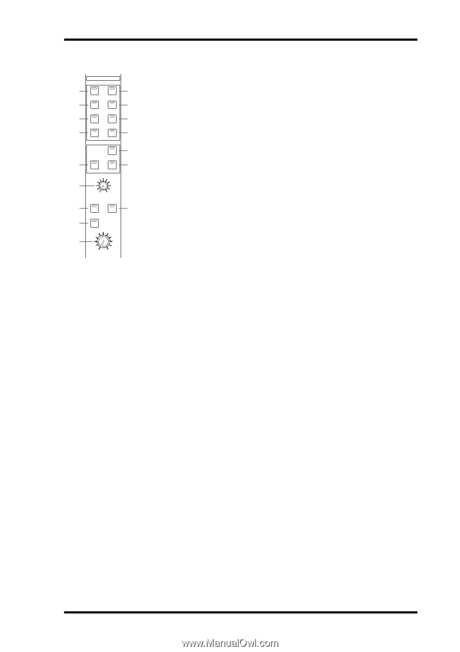
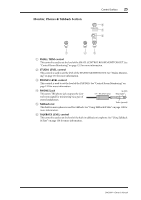
ASTEREO 2TR D1 button BSTEREO 2TR D2 button CSTEREO 2TR D3 button DSTEREO 2TR A1 button ESTEREO 2TR A2 button FSTEREO button GSTEREO ASSIGN 1 button HSTEREO ASSIGN 2 button ISURROUND BUS button JSURROUND ASSIGN 1 button KSURROUND ASSIGN 2 button LSURROUND
 |
View all Yamaha DM2000 manuals
Add to My Manuals
Save this manual to your list of manuals |
Page 41 highlights
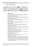
Control Surface 27 CONTROL ROOM 1 2 3 7 J CONTROL ROOM STEREO 2TR D1 2TR A1 2TR D2 2TR A2 2TR D3 STEREO ASSIGN 1 ASSIGN 2 SURROUND BUS ASSIGN 1 ASSIGN 2 4 5 6 8 9 K L M O SURROUND MONITOR LEVEL MONO DIMMER N SMALL P 0 10 CONTROL ROOM LEVEL A STEREO 2TR D1 button This button selects the 2TR IN DIGITAL AES/EBU 1 as the Control Room Monitor signal source. Its indicator lights up when this source is selected. See "Control Room Monitoring" on page 132 for more information. B STEREO 2TR D2 button This button selects the 2TR IN DIGITAL AES/EBU 2 as the Control Room Monitor signal source. Its indicator lights up when this source is selected. See "Control Room Monitoring" on page 132 for more information. C STEREO 2TR D3 button This button selects the 2TR IN DIGITAL COAXIAL 3 as the Control Room Monitor signal source. Its indicator lights up when this source is selected. See "Control Room Monitoring" on page 132 for more information. D STEREO 2TR A1 button This button selects the 2TR IN ANALOG 1 as the Control Room Monitor signal source. Its indicator lights up when this source is selected. See "Control Room Monitoring" on page 132 for more information. E STEREO 2TR A2 button This button selects the 2TR IN ANALOG 2 as the Control Room Monitor signal source. Its indicator lights up when this source is selected. See "Control Room Monitoring" on page 132 for more information. F STEREO button This button selects the Stereo Out as the Control Room Monitor signal source. Its indicator lights up when this source is selected. See "Control Room Monitoring" on page 132 for more information. G STEREO ASSIGN 1 button This button is used to select the assigned Output Channel as the Control Room Monitor signal source. Its indicator lights up when this source is selected. See "Control Room Setup" on page 133 for more information. H STEREO ASSIGN 2 button This button is used to select the assigned Output Channel as the Control Room Monitor signal source. Its indicator lights up when this source is selected. See "Control Room Setup" on page 133 for more information. I SURROUND BUS button This button is used to select the Bus Outs as the Surround Monitor signal source. Its indicator lights up when this source is selected. See "Surround Monitoring" on page 134 for more information. J SURROUND ASSIGN 1 button This button is used to select the assigned Slot's Inputs as the Surround Monitor signal source. Its indicator lights up when this source is selected. See "Surround Monitoring" on page 134 for more information. K SURROUND ASSIGN 2 button This button is used to select the assigned Slot's Inputs as the Surround Monitor signal source. Its indicator lights up when this source is selected. See "Surround Monitoring" on page 134 for more information. L SURROUND MONITOR LEVEL control This control is used to adjust the level of the Surround Monitor signals. See "Surround Monitoring" on page 134 for more information. DM2000-Owner's Manual
-
 1
1 -
2
-
3
-
4
-
5
-
6
-
7
-
8
-
9
-
10
-
11
-
12
-
13
-
14
-
15
-
16
-
17
-
18
-
19
-
20
-
21
-
22
-
23
-
24
-
25
-
26
-
27
-
28
-
29
-
30
-
31
-
32
-
33
-
34
-
35
-
 36
36 -
 37
37 -
 38
38 -
 39
39 -
 40
40 -
 41
41 -
 42
42 -
 43
43 -
 44
44 -
 45
45 -
 46
46 -
47
-
48
-
49
-
50
-
51
-
52
-
53
-
54
-
55
-
56
-
57
-
58
-
59
-
60
-
61
-
62
-
63
-
64
-
65
-
66
-
67
-
68
-
69
-
70
-
71
-
72
-
73
-
74
-
75
-
76
-
77
-
78
-
79
-
80
-
81
-
82
-
83
-
84
-
85
-
86
-
87
-
88
-
89
-
90
-
91
-
92
-
93
-
94
-
95
-
96
-
97
-
98
-
99
-
100
-
101
-
102
-
103
-
104
-
105
-
106
-
107
-
108
-
109
-
110
-
111
-
112
-
113
-
114
-
115
-
116
-
117
-
118
-
119
-
120
-
121
-
122
-
123
-
124
-
125
-
126
-
127
-
128
-
129
-
130
-
131
-
132
-
133
-
134
-
135
-
136
-
137
-
138
-
139
-
140
-
141
-
142
-
143
-
144
-
145
-
146
-
147
-
148
-
149
-
150
-
151
-
152
-
153
-
154
-
155
-
156
-
157
-
158
-
159
-
160
-
161
-
162
-
163
-
164
-
165
-
166
-
167
-
168
-
169
-
170
-
171
-
172
-
173
-
174
-
175
-
176
-
177
-
178
-
179
-
180
-
181
-
182
-
183
-
184
-
185
-
186
-
187
-
188
-
189
-
190
-
191
-
192
-
193
-
194
-
195
-
196
-
197
-
198
-
199
-
200
-
201
-
202
-
203
-
204
-
205
-
206
-
207
-
208
-
209
-
210
-
211
-
212
-
213
-
214
-
215
-
216
-
217
-
218
-
219
-
220
-
221
-
222
-
223
-
224
-
225
-
226
-
227
-
228
-
229
-
230
-
231
-
232
-
233
-
234
-
235
-
236
-
237
-
238
-
239
-
240
-
241
-
242
-
243
-
244
-
245
-
246
-
247
-
248
-
249
-
250
-
251
-
252
-
253
-
254
-
255
-
256
-
257
-
258
-
259
-
260
-
261
-
262
-
263
-
264
-
265
-
266
-
267
-
268
-
269
-
270
-
271
-
272
-
273
-
274
-
275
-
276
-
277
-
278
-
279
-
280
-
281
-
282
-
283
-
284
-
285
-
286
-
287
-
288
-
289
-
290
-
291
-
292
-
293
-
294
-
295
-
296
-
297
-
298
-
299
-
300
-
301
-
302
-
303
-
304
-
305
-
306
-
307
-
308
-
309
-
310
-
311
-
312
-
313
-
314
-
315
-
316
-
317
-
318
-
319
-
320
-
321
-
322
-
323
-
324
-
325
-
326
-
327
-
328
-
329
-
330
-
331
-
332
-
333
-
334
-
335
-
336
-
337
-
338
-
339
-
340
-
341
-
342
-
343
-
344
-
345
-
346
-
347
-
348
-
349
-
350
-
351
-
352
-
353
-
354
-
355
-
356
-
357
-
358
-
359
-
360
-
361
-
362
 |
 |