Yamaha DM2000 Owner's Manual - Page 327
I/O Slot Spec, Control I/O Spec
 |
View all Yamaha DM2000 manuals
Add to My Manuals
Save this manual to your list of manuals |
Page 327 highlights
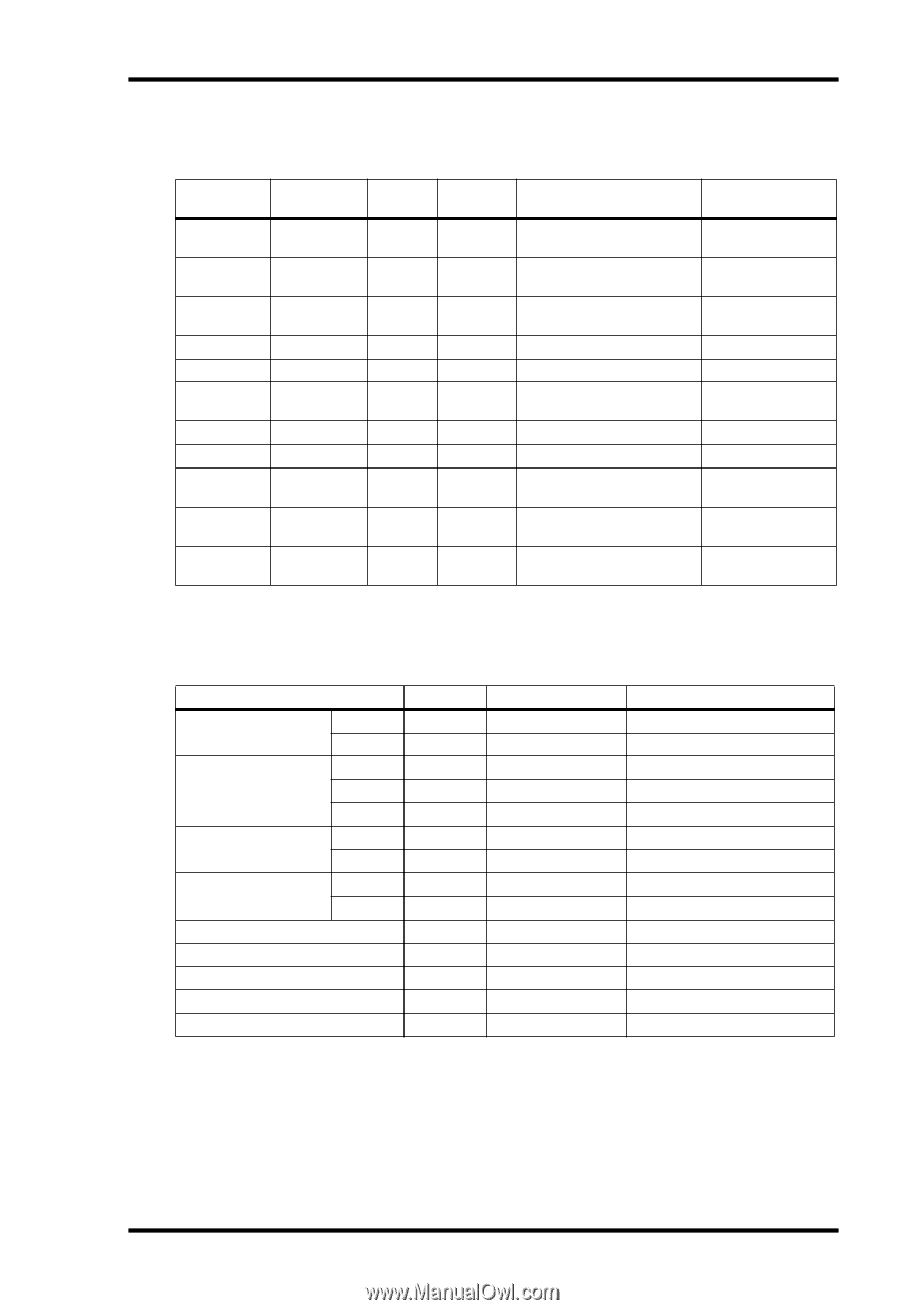
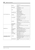
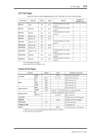
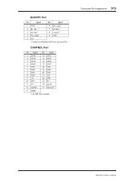
I/O Slot Spec 313 I/O Slot Spec Each I/O SLOT accepts a digital interface card. Only SLOT #1 has a serial interface. Card Name Function Accept MY8-AT ADAT YES MY8-TD TASCAM YES MY8-AE AES/EBU YES MY4-AD ANALOG IN YES MY8-AD ANALOG IN YES MY4-DA ANALOG OUT YES MY8-AD24 ANALOG IN YES MY8-AD96 ANALOG IN YES MY8-DA96 ANALOG OUT YES MY8-AE96S AES/EBU YES MY8-AE96 AES/EBU YES 1. See the Digital I/O chapter. Details depend on each interface card. Input 8 IN 8 IN 8 IN 4 IN 8 IN - 8 IN 8 IN - 8 IN 8 IN Output 8 OUT (depends on output patch)1 8 OUT (depends on output patch)1 8 OUT (depends on output patch)1 - - 4 OUT (depends on output patch)1 - - 8 OUT (depends on output patch)1 8 OUT (depends on output patch)1 8 OUT (depends on output patch)1 Number of available cards 6 6 6 6 6 6 6 6 6 4 6 Control I/O Spec I/O Port Format Level Connector in Console TO HOST MIDI TIME CODE IN WORD CLOCK CONTROL REMOTE KEYBOARD STORAGE CARD METER Serial USB IN OUT THRU MTC SMPTE IN OUT 1, 2 - USB 1.1 MIDI MIDI MIDI MIDI SMPTE - - - - PS/2 - - RS422 Mini DIN Connector 8P 0 V-3.3 V B type USB connector - DIN Connector 5P - DIN Connector 5P - DIN Connector 5P - DIN Connector 5P Nominal -10 dB/10k Ω XLR-3-31 type (Balanced)1 TTL/75 Ω (ON/OFF)2 BNC Connector TTL/75 Ω BNC Connector - D-SUB Connector 25P (Female) RS422 D-SUB Connector 9P (Male) - DIN Connector 6P - SmartMedia slot RS422 D-SUB Connector 15P (Female) 1. XLR-3-31 type connectors are balanced (1=GND, 2=HOT, 3=COLD). 2. This switch is on the rear panel. DM2000-Owner's Manual
-
 1
1 -
2
-
3
-
4
-
5
-
6
-
7
-
8
-
9
-
10
-
11
-
12
-
13
-
14
-
15
-
16
-
17
-
18
-
19
-
20
-
21
-
22
-
23
-
24
-
25
-
26
-
27
-
28
-
29
-
30
-
31
-
32
-
33
-
34
-
35
-
36
-
37
-
38
-
39
-
40
-
41
-
42
-
43
-
44
-
45
-
46
-
47
-
48
-
49
-
50
-
51
-
52
-
53
-
54
-
55
-
56
-
57
-
58
-
59
-
60
-
61
-
62
-
63
-
64
-
65
-
66
-
67
-
68
-
69
-
70
-
71
-
72
-
73
-
74
-
75
-
76
-
77
-
78
-
79
-
80
-
81
-
82
-
83
-
84
-
85
-
86
-
87
-
88
-
89
-
90
-
91
-
92
-
93
-
94
-
95
-
96
-
97
-
98
-
99
-
100
-
101
-
102
-
103
-
104
-
105
-
106
-
107
-
108
-
109
-
110
-
111
-
112
-
113
-
114
-
115
-
116
-
117
-
118
-
119
-
120
-
121
-
122
-
123
-
124
-
125
-
126
-
127
-
128
-
129
-
130
-
131
-
132
-
133
-
134
-
135
-
136
-
137
-
138
-
139
-
140
-
141
-
142
-
143
-
144
-
145
-
146
-
147
-
148
-
149
-
150
-
151
-
152
-
153
-
154
-
155
-
156
-
157
-
158
-
159
-
160
-
161
-
162
-
163
-
164
-
165
-
166
-
167
-
168
-
169
-
170
-
171
-
172
-
173
-
174
-
175
-
176
-
177
-
178
-
179
-
180
-
181
-
182
-
183
-
184
-
185
-
186
-
187
-
188
-
189
-
190
-
191
-
192
-
193
-
194
-
195
-
196
-
197
-
198
-
199
-
200
-
201
-
202
-
203
-
204
-
205
-
206
-
207
-
208
-
209
-
210
-
211
-
212
-
213
-
214
-
215
-
216
-
217
-
218
-
219
-
220
-
221
-
222
-
223
-
224
-
225
-
226
-
227
-
228
-
229
-
230
-
231
-
232
-
233
-
234
-
235
-
236
-
237
-
238
-
239
-
240
-
241
-
242
-
243
-
244
-
245
-
246
-
247
-
248
-
249
-
250
-
251
-
252
-
253
-
254
-
255
-
256
-
257
-
258
-
259
-
260
-
261
-
262
-
263
-
264
-
265
-
266
-
267
-
268
-
269
-
270
-
271
-
272
-
273
-
274
-
275
-
276
-
277
-
278
-
279
-
280
-
281
-
282
-
283
-
284
-
285
-
286
-
287
-
288
-
289
-
290
-
291
-
292
-
293
-
294
-
295
-
296
-
297
-
298
-
299
-
300
-
301
-
302
-
303
-
304
-
305
-
306
-
307
-
308
-
309
-
310
-
311
-
312
-
313
-
314
-
315
-
316
-
317
-
318
-
319
-
320
-
321
-
 322
322 -
 323
323 -
 324
324 -
 325
325 -
 326
326 -
 327
327 -
 328
328 -
 329
329 -
 330
330 -
 331
331 -
 332
332 -
333
-
334
-
335
-
336
-
337
-
338
-
339
-
340
-
341
-
342
-
343
-
344
-
345
-
346
-
347
-
348
-
349
-
350
-
351
-
352
-
353
-
354
-
355
-
356
-
357
-
358
-
359
-
360
-
361
-
362
 |
 |