Yamaha DM2000 Owner's Manual - Page 218
Assigning Outputs to Channels, Setting Channel Levels
 |
View all Yamaha DM2000 manuals
Add to My Manuals
Save this manual to your list of manuals |
Page 218 highlights
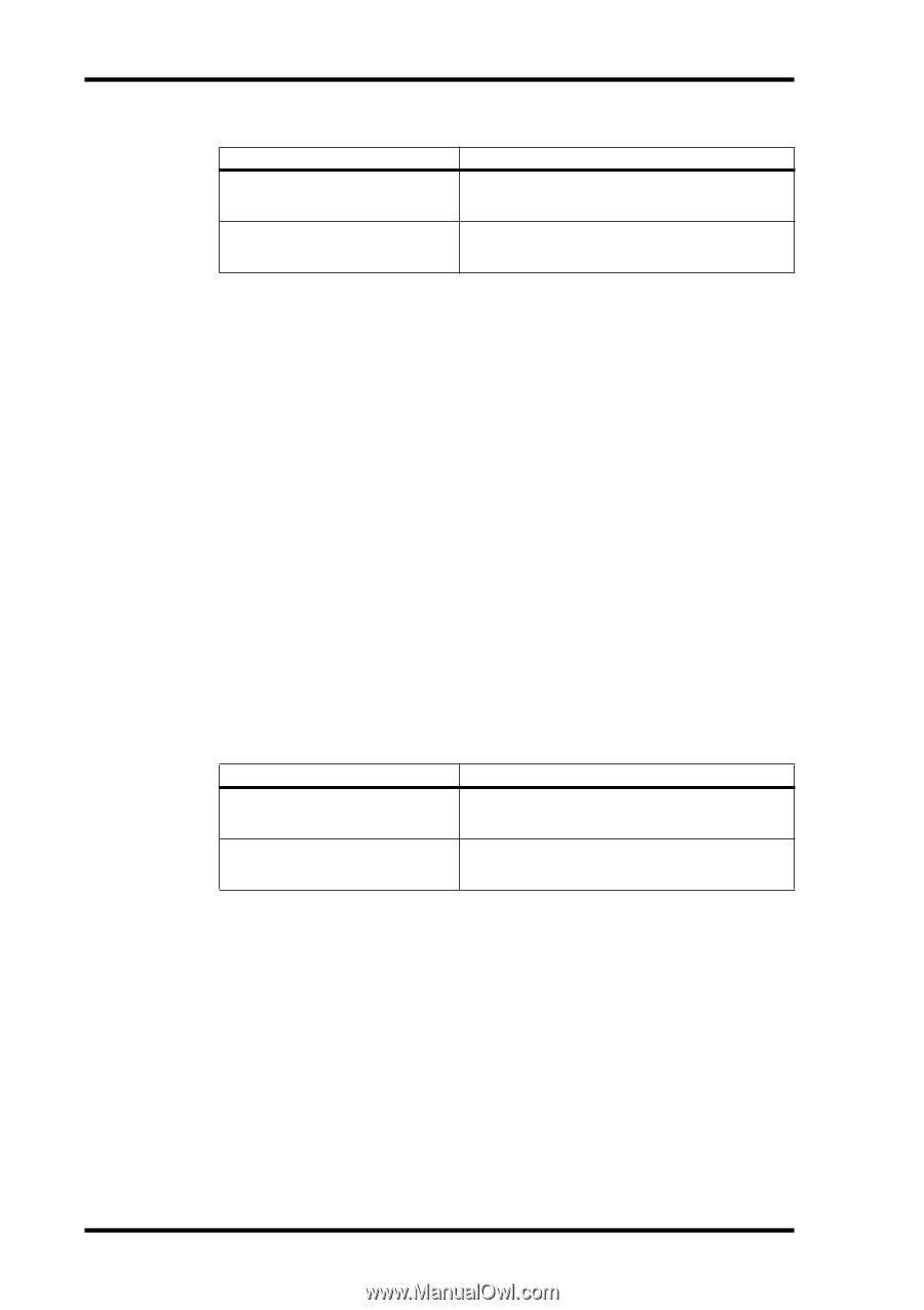
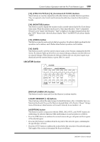
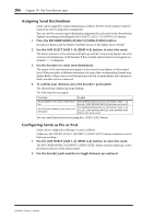
204 Chapter 19-Pro Tools Remote Layer The following shortcuts apply. To do this... Do this! Set all channels to the same input source Set all selected channels to the same input source ENCODER MODE [ASSIGN 3], ENCODER MODE [ASSIGN 1], Encoder, USER DEFINED KEYS [5]+Encoder push-switch ENCODER MODE [ASSIGN 3], ENCODER MODE [ASSIGN 1], Encoder, USER DEFINED KEYS [5]+USER DEFINED KEYS [4]+Encoder push-switch You can cancel this function by pressing the [-/DEC] (ESC) button. Assigning Outputs to Channels Channels can be assigned to output destinations as follows. The Pro Tools transport must be stopped in order to make these assignments. You can view the current output destination assignment for each channel on the channel strip displays by pressing and holding the ENCODER MODE [ASSIGN 2] (OUTPUT) button. 1 Press the ENCODER MODE [ASSIGN 3] (SEND ASSIGN) button. Its indicator flashes, and the SELECT ASSIGN section of the display shows "ASGN." 2 Press the ENCODER MODE [ASSIGN 2] (OUTPUT) button. Its indicator lights up, and the channel strip displays show the current output destination for each channel. 3 Use the Encoders to select output destinations. The names of the output destinations appear on the channel strip displays in abbreviated form. When you select a destination other than the current, the ring of the corresponding channel strip display flashes. 4 To confirm your selection, press the Encoder's push-switch. The channel strip display ring stops flashing. The following shortcuts apply. To do this... Do this! Set all channels to the same output destination ENCODER MODE [ASSIGN 3], ENCODER MODE [ASSIGN 2], Encoder, USER DEFINED KEYS [5]+Encoder push-switch Set all selected channels to the same output destination ENCODER MODE [ASSIGN 3], ENCODER MODE [ASSIGN 2], Encoder, USER DEFINED KEYS [5]+USER DEFINED KEYS [4]+Encoder push-switch You can cancel this function by pressing the [-/DEC] (ESC) button. Setting Channel Levels Channel levels can be set as follows. (Make sure the FADER MODE [FADER] and [AUX/MTRX] button indicators are not flashing before proceeding.) 1 Use the faders to set channels levels. Faders in a mix group are controlled together. You can temporarily disable a mix group in order to make adjustments to individual faders by pressing and holding the USER DEFINED KEYS [12] (CTRL/CLUTCH) button. Alternatively, you can make adjustments to individual faders while touching the knob of at least one fader in that mix group. You can view channel levels in dB on the channel strip displays by holding down the USER DEFINED KEYS [13] (ALT/FINE) button while adjusting faders. DM2000-Owner's Manual
-
 1
1 -
2
-
3
-
4
-
5
-
6
-
7
-
8
-
9
-
10
-
11
-
12
-
13
-
14
-
15
-
16
-
17
-
18
-
19
-
20
-
21
-
22
-
23
-
24
-
25
-
26
-
27
-
28
-
29
-
30
-
31
-
32
-
33
-
34
-
35
-
36
-
37
-
38
-
39
-
40
-
41
-
42
-
43
-
44
-
45
-
46
-
47
-
48
-
49
-
50
-
51
-
52
-
53
-
54
-
55
-
56
-
57
-
58
-
59
-
60
-
61
-
62
-
63
-
64
-
65
-
66
-
67
-
68
-
69
-
70
-
71
-
72
-
73
-
74
-
75
-
76
-
77
-
78
-
79
-
80
-
81
-
82
-
83
-
84
-
85
-
86
-
87
-
88
-
89
-
90
-
91
-
92
-
93
-
94
-
95
-
96
-
97
-
98
-
99
-
100
-
101
-
102
-
103
-
104
-
105
-
106
-
107
-
108
-
109
-
110
-
111
-
112
-
113
-
114
-
115
-
116
-
117
-
118
-
119
-
120
-
121
-
122
-
123
-
124
-
125
-
126
-
127
-
128
-
129
-
130
-
131
-
132
-
133
-
134
-
135
-
136
-
137
-
138
-
139
-
140
-
141
-
142
-
143
-
144
-
145
-
146
-
147
-
148
-
149
-
150
-
151
-
152
-
153
-
154
-
155
-
156
-
157
-
158
-
159
-
160
-
161
-
162
-
163
-
164
-
165
-
166
-
167
-
168
-
169
-
170
-
171
-
172
-
173
-
174
-
175
-
176
-
177
-
178
-
179
-
180
-
181
-
182
-
183
-
184
-
185
-
186
-
187
-
188
-
189
-
190
-
191
-
192
-
193
-
194
-
195
-
196
-
197
-
198
-
199
-
200
-
201
-
202
-
203
-
204
-
205
-
206
-
207
-
208
-
209
-
210
-
211
-
212
-
 213
213 -
 214
214 -
 215
215 -
 216
216 -
 217
217 -
 218
218 -
 219
219 -
 220
220 -
 221
221 -
 222
222 -
 223
223 -
224
-
225
-
226
-
227
-
228
-
229
-
230
-
231
-
232
-
233
-
234
-
235
-
236
-
237
-
238
-
239
-
240
-
241
-
242
-
243
-
244
-
245
-
246
-
247
-
248
-
249
-
250
-
251
-
252
-
253
-
254
-
255
-
256
-
257
-
258
-
259
-
260
-
261
-
262
-
263
-
264
-
265
-
266
-
267
-
268
-
269
-
270
-
271
-
272
-
273
-
274
-
275
-
276
-
277
-
278
-
279
-
280
-
281
-
282
-
283
-
284
-
285
-
286
-
287
-
288
-
289
-
290
-
291
-
292
-
293
-
294
-
295
-
296
-
297
-
298
-
299
-
300
-
301
-
302
-
303
-
304
-
305
-
306
-
307
-
308
-
309
-
310
-
311
-
312
-
313
-
314
-
315
-
316
-
317
-
318
-
319
-
320
-
321
-
322
-
323
-
324
-
325
-
326
-
327
-
328
-
329
-
330
-
331
-
332
-
333
-
334
-
335
-
336
-
337
-
338
-
339
-
340
-
341
-
342
-
343
-
344
-
345
-
346
-
347
-
348
-
349
-
350
-
351
-
352
-
353
-
354
-
355
-
356
-
357
-
358
-
359
-
360
-
361
-
362
 |
 |