Garmin G2000 Pilots Guide - Page 15
System overview, 1.1 System Description
 |
View all Garmin G2000 manuals
Add to My Manuals
Save this manual to your list of manuals |
Page 15 highlights
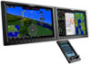
SYSTTEEMM OVERVIIEEWW FLIGHT INSTRUMMEENTS EEIIS AAUUDD&IIOOCNP&ASCNNESL FLIGHT MANAGEEMMEENT System Overview Section 1 System overview 1.1 System Description This section provides an overview of the Garmin G2000 Integrated Avionics System as installed in the Cessna Model T240 aircraft. The G2000 is an integrated flight control system that presents flight instrumentation, position, navigation, communication, and identification information to the pilot using flat-panel color displays and a Touchscreen Controller. The system consists of the following Line Replaceable Units (LRUs): • GDU 1400W (2) - The GDU 1400W features a 14-inch light emitting diode (LED) backlit widescreen display with a 1280 x 800 resolution. The GDU 1400W installed on the left/pilot side is designated as the Primary Flight Display (PFD) and the unit installed on the right/copilot side is designated as the Multi Function Display (MFD). The GDUs communicate with each other through a High-Speed Data Bus (HSDB) Ethernet connection. Each GDU is also paired with a HSDB connection to the on-side GIA 63W Integrated Avionics Unit (IAU). •GTC 570 (1) - The Touchscreen Controller provides MFD control, PFD display pane control, in addition to FMS functions, data entry interface, and communications and environmental control to the system. The Touchscreen Controller communicates with each GDU and to the GMA 36 through an HSDB connection. • GCU 275 - The GDU Controller provides PFD control, radio tuning, and PFD Display Pane control through an RS-232 digital interface. • GMA 36 - The Remote Audio Unit integrates navigation/communication radio (NAV/COM) digital audio, intercom, and marker beacon audio. This unit communicates with both IAUs using an RS-232 digital interface and the Touchscreen Controller through the HSDB connection. • GIA 63W (2) - The Integrated Avionics Units (IAU) function as the main communications hub, linking several LRUs with the GDUs. Each IAU contains a GPS SBAS (Satellite-Based Augmentation System) receiver, a very high frequency (VHF) communication/navigation/glideslope (COM/NAV/GS) receiver, a flight director (FD), and system integration microprocessors, and is paired with the on-side GDU via an HSDB connection. The IAUs are not paired and do not communicate with each other directly. • GDC 74A - The Air Data Computer (ADC) processes data from the pitot/static system and outside air temperature (OAT) sensor. The ADC provides pressure altitude, airspeed, vertical speed, and OAT information to the system. It communicates with the #1 IAU using an RS-232 digital interface, and to each IAU, GDU, and GRS 77 unit via ARINC 429 digital connections. • GEA 71 - The Engine Airframe Unit receives and processes signals from the engine and airframe sensors. This unit communicates with both IAUs using an RS-485 digital interface. • GTX 33 ES - The solid-state Transponder provides Modes A, C, and S capability and communicates with both IAUs through an RS-232 digital interface. • GRS 77 (2) - The Attitude and Heading Reference System (AHRS) provides aircraft attitude and heading information via ARINC 429 to the PFD, MFD, and the IAUs. The AHRS contains advanced sensors (including accelerometers and rate sensors) and interfaces with the Magnetometer to obtain magnetic field information, with the ADC to obtain air data, and with both IAUs to obtain GPS information. AHRS operation is discussed in System Operation, later in this section. HAZARD AVOIDANCE AFCS ADDITIONAL FEATURES APPENDICES INDEX 190-01263-01 Rev. A Garmin G2000 Pilot's Guide for the Cessna T240 1
-
 1
1 -
2
-
3
-
4
-
5
-
6
-
7
-
8
-
9
-
 10
10 -
 11
11 -
 12
12 -
 13
13 -
 14
14 -
 15
15 -
 16
16 -
 17
17 -
 18
18 -
 19
19 -
 20
20 -
21
-
22
-
23
-
24
-
25
-
26
-
27
-
28
-
29
-
30
-
31
-
32
-
33
-
34
-
35
-
36
-
37
-
38
-
39
-
40
-
41
-
42
-
43
-
44
-
45
-
46
-
47
-
48
-
49
-
50
-
51
-
52
-
53
-
54
-
55
-
56
-
57
-
58
-
59
-
60
-
61
-
62
-
63
-
64
-
65
-
66
-
67
-
68
-
69
-
70
-
71
-
72
-
73
-
74
-
75
-
76
-
77
-
78
-
79
-
80
-
81
-
82
-
83
-
84
-
85
-
86
-
87
-
88
-
89
-
90
-
91
-
92
-
93
-
94
-
95
-
96
-
97
-
98
-
99
-
100
-
101
-
102
-
103
-
104
-
105
-
106
-
107
-
108
-
109
-
110
-
111
-
112
-
113
-
114
-
115
-
116
-
117
-
118
-
119
-
120
-
121
-
122
-
123
-
124
-
125
-
126
-
127
-
128
-
129
-
130
-
131
-
132
-
133
-
134
-
135
-
136
-
137
-
138
-
139
-
140
-
141
-
142
-
143
-
144
-
145
-
146
-
147
-
148
-
149
-
150
-
151
-
152
-
153
-
154
-
155
-
156
-
157
-
158
-
159
-
160
-
161
-
162
-
163
-
164
-
165
-
166
-
167
-
168
-
169
-
170
-
171
-
172
-
173
-
174
-
175
-
176
-
177
-
178
-
179
-
180
-
181
-
182
-
183
-
184
-
185
-
186
-
187
-
188
-
189
-
190
-
191
-
192
-
193
-
194
-
195
-
196
-
197
-
198
-
199
-
200
-
201
-
202
-
203
-
204
-
205
-
206
-
207
-
208
-
209
-
210
-
211
-
212
-
213
-
214
-
215
-
216
-
217
-
218
-
219
-
220
-
221
-
222
-
223
-
224
-
225
-
226
-
227
-
228
-
229
-
230
-
231
-
232
-
233
-
234
-
235
-
236
-
237
-
238
-
239
-
240
-
241
-
242
-
243
-
244
-
245
-
246
-
247
-
248
-
249
-
250
-
251
-
252
-
253
-
254
-
255
-
256
-
257
-
258
-
259
-
260
-
261
-
262
-
263
-
264
-
265
-
266
-
267
-
268
-
269
-
270
-
271
-
272
-
273
-
274
-
275
-
276
-
277
-
278
-
279
-
280
-
281
-
282
-
283
-
284
-
285
-
286
-
287
-
288
-
289
-
290
-
291
-
292
-
293
-
294
-
295
-
296
-
297
-
298
-
299
-
300
-
301
-
302
-
303
-
304
-
305
-
306
-
307
-
308
-
309
-
310
-
311
-
312
-
313
-
314
-
315
-
316
-
317
-
318
-
319
-
320
-
321
-
322
-
323
-
324
-
325
-
326
-
327
-
328
-
329
-
330
-
331
-
332
-
333
-
334
-
335
-
336
-
337
-
338
-
339
-
340
-
341
-
342
-
343
-
344
-
345
-
346
-
347
-
348
-
349
-
350
-
351
-
352
-
353
-
354
-
355
-
356
-
357
-
358
-
359
-
360
-
361
-
362
-
363
-
364
-
365
-
366
-
367
-
368
-
369
-
370
-
371
-
372
-
373
-
374
-
375
-
376
-
377
-
378
-
379
-
380
-
381
-
382
-
383
-
384
-
385
-
386
-
387
-
388
-
389
-
390
-
391
-
392
-
393
-
394
-
395
-
396
-
397
-
398
-
399
-
400
-
401
-
402
-
403
-
404
-
405
-
406
-
407
-
408
-
409
-
410
-
411
-
412
-
413
-
414
-
415
-
416
-
417
-
418
-
419
-
420
-
421
-
422
-
423
-
424
-
425
-
426
-
427
-
428
-
429
-
430
-
431
-
432
-
433
-
434
-
435
-
436
-
437
-
438
-
439
-
440
-
441
-
442
-
443
-
444
-
445
-
446
-
447
-
448
-
449
-
450
-
451
-
452
-
453
-
454
-
455
-
456
-
457
-
458
-
459
-
460
-
461
-
462
-
463
-
464
-
465
-
466
-
467
-
468
-
469
-
470
-
471
-
472
-
473
-
474
-
475
-
476
-
477
-
478
-
479
-
480
-
481
-
482
-
483
-
484
-
485
-
486
-
487
-
488
-
489
-
490
-
491
-
492
-
493
-
494
-
495
-
496
-
497
-
498
-
499
-
500
-
501
-
502
-
503
-
504
-
505
-
506
-
507
-
508
-
509
-
510
-
511
-
512
-
513
-
514
-
515
-
516
-
517
-
518
-
519
-
520
-
521
-
522
-
523
-
524
-
525
-
526
-
527
-
528
-
529
-
530
-
531
-
532
-
533
-
534
-
535
-
536
-
537
-
538
-
539
-
540
-
541
-
542
-
543
-
544
-
545
-
546
-
547
-
548
-
549
-
550
-
551
-
552
-
553
-
554
-
555
-
556
-
557
-
558
-
559
-
560
-
561
-
562
-
563
-
564
-
565
-
566
-
567
-
568
-
569
-
570
-
571
-
572
-
573
-
574
-
575
-
576
-
577
-
578
-
579
-
580
-
581
-
582
-
583
-
584
-
585
-
586
-
587
-
588
-
589
-
590
-
591
-
592
-
593
-
594
-
595
-
596
-
597
-
598
-
599
-
600
-
601
-
602
-
603
-
604
-
605
-
606
-
607
-
608
-
609
-
610
-
611
-
612
-
613
-
614
-
615
-
616
-
617
-
618
-
619
-
620
-
621
-
622
-
623
-
624
 |
 |
