HP Xw6600 HP xw6600 Workstation Service and Technical Reference Guide - Page 105
The hard drive body should be securely mounted within the mounting bracket.
 |
UPC - 883585731121
View all HP Xw6600 manuals
Add to My Manuals
Save this manual to your list of manuals |
Page 105 highlights
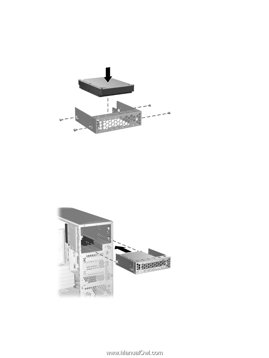
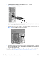
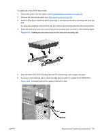
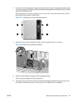
5. As shown in the following figure, place the SATA hard drive in the drive bracket, and align the four threaded screw holes in the hard drive body with the four matching screw holes in the inner bracket flanges. Figure 4-54 Installing the hard drive in bracket 6. Install four silver ANSI 6-32 screws through the oversized holes in the bracket outer flanges, and into the bracket inner flanges and hard drive body, as shown in the figure above. The hard drive body should be securely mounted within the mounting bracket. 7. As shown in the following figure, lift the locking lever on the left as you start to insert the drive and bracket into the respective optical drive bay until it locks into place, and then check for secure fit. Figure 4-55 Installing the hard drive in an optical drive bay ENWW Removing and replacing components 95
-
 1
1 -
2
-
3
-
4
-
5
-
6
-
7
-
8
-
9
-
10
-
11
-
12
-
13
-
14
-
15
-
16
-
17
-
18
-
19
-
20
-
21
-
22
-
23
-
24
-
25
-
26
-
27
-
28
-
29
-
30
-
31
-
32
-
33
-
34
-
35
-
36
-
37
-
38
-
39
-
40
-
41
-
42
-
43
-
44
-
45
-
46
-
47
-
48
-
49
-
50
-
51
-
52
-
53
-
54
-
55
-
56
-
57
-
58
-
59
-
60
-
61
-
62
-
63
-
64
-
65
-
66
-
67
-
68
-
69
-
70
-
71
-
72
-
73
-
74
-
75
-
76
-
77
-
78
-
79
-
80
-
81
-
82
-
83
-
84
-
85
-
86
-
87
-
88
-
89
-
90
-
91
-
92
-
93
-
94
-
95
-
96
-
97
-
98
-
99
-
 100
100 -
 101
101 -
 102
102 -
 103
103 -
 104
104 -
 105
105 -
 106
106 -
 107
107 -
 108
108 -
 109
109 -
 110
110 -
111
-
112
-
113
-
114
-
115
-
116
-
117
-
118
-
119
-
120
-
121
-
122
-
123
-
124
-
125
-
126
-
127
-
128
-
129
-
130
-
131
-
132
-
133
-
134
-
135
-
136
-
137
-
138
-
139
-
140
-
141
-
142
-
143
-
144
-
145
-
146
-
147
-
148
-
149
-
150
-
151
-
152
-
153
-
154
-
155
-
156
-
157
-
158
-
159
-
160
-
161
-
162
-
163
-
164
-
165
-
166
-
167
-
168
-
169
-
170
 |
 |