HP Xw6600 HP xw6600 Workstation Service and Technical Reference Guide - Page 69
Smart Cover Lock solenoid (optional), Removing the workstation top cover
 |
UPC - 883585731121
View all HP Xw6600 manuals
Add to My Manuals
Save this manual to your list of manuals |
Page 69 highlights
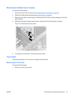
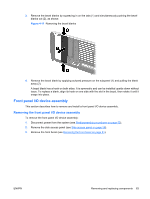
To reinstall the side access panel, align the bottom groove of the side access panel with the bottom edge of the chassis, rotate the side access panel toward the chassis and press firmly until the latch engages. Smart Cover Lock solenoid (optional) This section describes how to remove the workstation top cover and Smart Cover Lock solenoid Removing the workstation top cover Remove the workstation top cover before removing the Smart Cover Lock solenoid. To remove the top cover: 1. Disconnect power from the system (see Predisassembly procedures on page 52). CAUTION: Use care when prying up the workstation top cover. Installation locking tangs might break off if the top cover is pried upward more than 0.5 cm (0.2 in). 2. Remove the side access panel (see Side access panel on page 58). 3. Remove the front bezel (see Front bezel on page 61). 4. Push the blade of a flat blade screw driver into the recessed tab of the top cover on the rear of the chassis and gently push the screw driver handle downward (1) to pry the top cover upward approximately 0.5 cm (0.2 in). 5. With the screw driver inserted and prying upward, use the palm of your hand to push against the front edge of the top cover. Push the top cover toward the rear of the workstation chassis. This releases the six locking hooks located on the underside of the top cover and allows it to slide toward the rear of the chassis approximately 1.25 cm (0.5 in). Lift the cover from the chassis (2) and store it for later reuse, as shown: Figure 4-7 Removing the top cover Removing the Smart Cover Lock solenoid To remove the Smart Cover Lock solenoid: ENWW Removing and replacing components 59
-
 1
1 -
2
-
3
-
4
-
5
-
6
-
7
-
8
-
9
-
10
-
11
-
12
-
13
-
14
-
15
-
16
-
17
-
18
-
19
-
20
-
21
-
22
-
23
-
24
-
25
-
26
-
27
-
28
-
29
-
30
-
31
-
32
-
33
-
34
-
35
-
36
-
37
-
38
-
39
-
40
-
41
-
42
-
43
-
44
-
45
-
46
-
47
-
48
-
49
-
50
-
51
-
52
-
53
-
54
-
55
-
56
-
57
-
58
-
59
-
60
-
61
-
62
-
63
-
 64
64 -
 65
65 -
 66
66 -
 67
67 -
 68
68 -
 69
69 -
 70
70 -
 71
71 -
 72
72 -
 73
73 -
 74
74 -
75
-
76
-
77
-
78
-
79
-
80
-
81
-
82
-
83
-
84
-
85
-
86
-
87
-
88
-
89
-
90
-
91
-
92
-
93
-
94
-
95
-
96
-
97
-
98
-
99
-
100
-
101
-
102
-
103
-
104
-
105
-
106
-
107
-
108
-
109
-
110
-
111
-
112
-
113
-
114
-
115
-
116
-
117
-
118
-
119
-
120
-
121
-
122
-
123
-
124
-
125
-
126
-
127
-
128
-
129
-
130
-
131
-
132
-
133
-
134
-
135
-
136
-
137
-
138
-
139
-
140
-
141
-
142
-
143
-
144
-
145
-
146
-
147
-
148
-
149
-
150
-
151
-
152
-
153
-
154
-
155
-
156
-
157
-
158
-
159
-
160
-
161
-
162
-
163
-
164
-
165
-
166
-
167
-
168
-
169
-
170
 |
 |