HP Xw6600 HP xw6600 Workstation Service and Technical Reference Guide - Page 70
Replacing the smart cover lock solenoid, Reinstalling the workstation top cover
 |
UPC - 883585731121
View all HP Xw6600 manuals
Add to My Manuals
Save this manual to your list of manuals |
Page 70 highlights
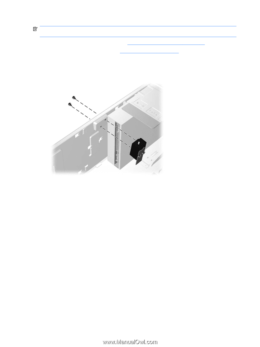
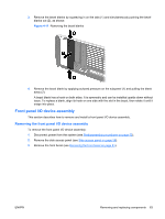
NOTE: To purchase a FailSafe key, contact your authorized HP reseller or service provider, or see the HP Web site for ordering information. 1. Disconnect power from the system (see Predisassembly procedures on page 52). 2. Remove the side access panel (see Side access panel on page 58). 3. Remove top cover. 4. Disconnect the solenoid cable from the system board (1), as shown: Figure 4-8 Removing the Smart Cover Lock solenoid assembly 5. Use the FailSafe key (T-15 wrench) to remove the two screws from the back of the chassis (2). 6. Slide the solenoid assembly away from the chassis and out of the workstation (3). Replacing the smart cover lock solenoid To replace the Smart Cover Lock Solenoid assembly, reverse the previous removal steps. Reinstalling the workstation top cover To reinstall the workstation top cover: 1. Place the top cover on top of the workstation chassis and align the six locking hooks on the underside of the cover. Ensure that the locking hooks insert into the latch openings on the top of the chassis. Ensure that the open end of each locking hooks is facing toward the workstation front panel. 2. With the locking hooks inserted into the latch openings, push the top cover forward toward the front panel of the chassis until it snaps into the locked position. 3. Reinstall the front bezel and the workstation side access panel. 60 Chapter 4 Removal and replacement procedures ENWW
-
 1
1 -
2
-
3
-
4
-
5
-
6
-
7
-
8
-
9
-
10
-
11
-
12
-
13
-
14
-
15
-
16
-
17
-
18
-
19
-
20
-
21
-
22
-
23
-
24
-
25
-
26
-
27
-
28
-
29
-
30
-
31
-
32
-
33
-
34
-
35
-
36
-
37
-
38
-
39
-
40
-
41
-
42
-
43
-
44
-
45
-
46
-
47
-
48
-
49
-
50
-
51
-
52
-
53
-
54
-
55
-
56
-
57
-
58
-
59
-
60
-
61
-
62
-
63
-
64
-
 65
65 -
 66
66 -
 67
67 -
 68
68 -
 69
69 -
 70
70 -
 71
71 -
 72
72 -
 73
73 -
 74
74 -
 75
75 -
76
-
77
-
78
-
79
-
80
-
81
-
82
-
83
-
84
-
85
-
86
-
87
-
88
-
89
-
90
-
91
-
92
-
93
-
94
-
95
-
96
-
97
-
98
-
99
-
100
-
101
-
102
-
103
-
104
-
105
-
106
-
107
-
108
-
109
-
110
-
111
-
112
-
113
-
114
-
115
-
116
-
117
-
118
-
119
-
120
-
121
-
122
-
123
-
124
-
125
-
126
-
127
-
128
-
129
-
130
-
131
-
132
-
133
-
134
-
135
-
136
-
137
-
138
-
139
-
140
-
141
-
142
-
143
-
144
-
145
-
146
-
147
-
148
-
149
-
150
-
151
-
152
-
153
-
154
-
155
-
156
-
157
-
158
-
159
-
160
-
161
-
162
-
163
-
164
-
165
-
166
-
167
-
168
-
169
-
170
 |
 |