HP Xw6600 HP xw6600 Workstation Service and Technical Reference Guide - Page 112
Installing the battery, Replacing the system board,
 |
UPC - 883585731121
View all HP Xw6600 manuals
Add to My Manuals
Save this manual to your list of manuals |
Page 112 highlights
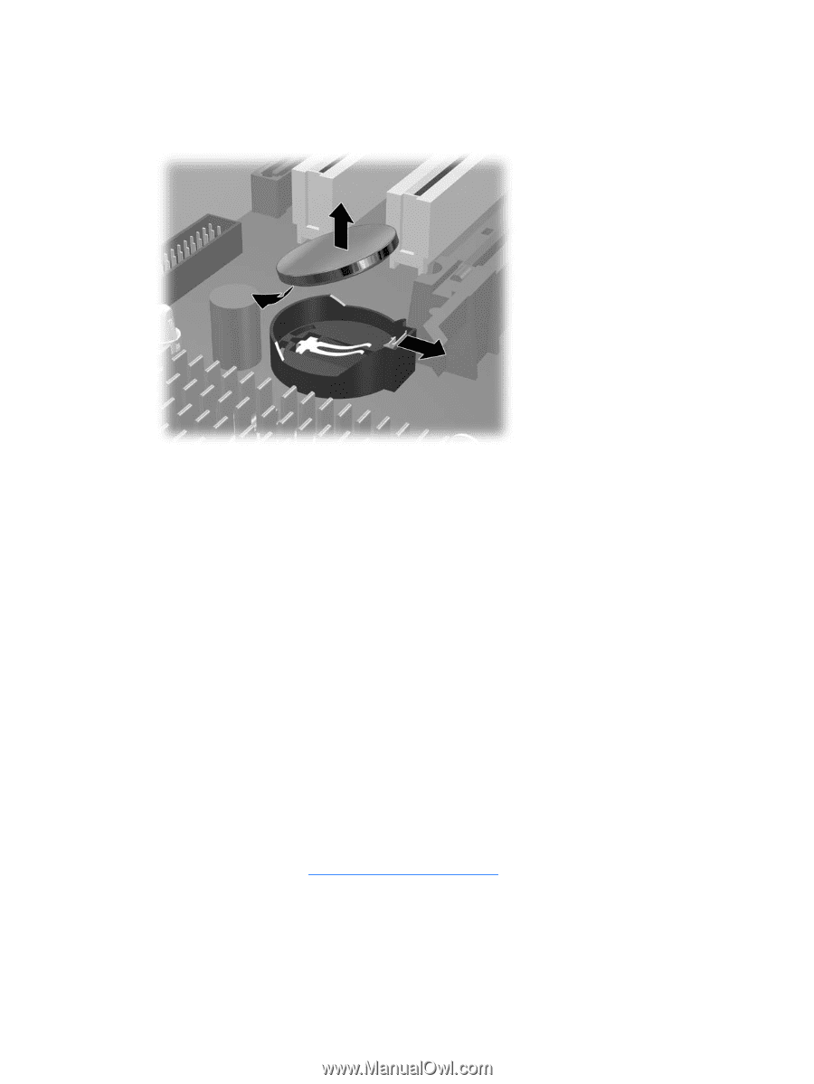
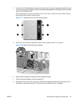
3. On the system board, press outward on the release tab of the battery holder, as shown in the following figure. Figure 4-62 Removing the battery 4. Rotate the battery enough to get beyond the latch, and then lift it straight up. Installing the battery To install the battery: 1. Confirm the polarity (positive or negative) of the battery to position it correctly in the battery holder. 2. Place the battery edge under the plastic housing tab. 3. Press down on the battery until the metal snaps engage. Replacing the system board 1. With the workstation chassis laying flat (access opening facing upward) and the system board held horizontally (component side up), orient the system board so that the I/O connectors are facing the rear of the chassis. Carefully lower the system board into the chassis and ensure all system board standoffs engage with mating keyholes in the chassis. 2. Ensure that the system board connectors engage correctly with the rear I/O panel. 3. While maintaining an even downward pressure, push the system board back into the rear I/O chassis openings until the heat sink screw holes line up, then install the heat sinks while holding pressure against the system board to keep the holes aligned and making certain that all system board standoffs remain engaged. 4. Install the heatsinks (see Processor heatsink on page 96), and all PCIe and PCI cards. 102 Chapter 4 Removal and replacement procedures ENWW
-
 1
1 -
2
-
3
-
4
-
5
-
6
-
7
-
8
-
9
-
10
-
11
-
12
-
13
-
14
-
15
-
16
-
17
-
18
-
19
-
20
-
21
-
22
-
23
-
24
-
25
-
26
-
27
-
28
-
29
-
30
-
31
-
32
-
33
-
34
-
35
-
36
-
37
-
38
-
39
-
40
-
41
-
42
-
43
-
44
-
45
-
46
-
47
-
48
-
49
-
50
-
51
-
52
-
53
-
54
-
55
-
56
-
57
-
58
-
59
-
60
-
61
-
62
-
63
-
64
-
65
-
66
-
67
-
68
-
69
-
70
-
71
-
72
-
73
-
74
-
75
-
76
-
77
-
78
-
79
-
80
-
81
-
82
-
83
-
84
-
85
-
86
-
87
-
88
-
89
-
90
-
91
-
92
-
93
-
94
-
95
-
96
-
97
-
98
-
99
-
100
-
101
-
102
-
103
-
104
-
105
-
106
-
 107
107 -
 108
108 -
 109
109 -
 110
110 -
 111
111 -
 112
112 -
 113
113 -
 114
114 -
 115
115 -
 116
116 -
 117
117 -
118
-
119
-
120
-
121
-
122
-
123
-
124
-
125
-
126
-
127
-
128
-
129
-
130
-
131
-
132
-
133
-
134
-
135
-
136
-
137
-
138
-
139
-
140
-
141
-
142
-
143
-
144
-
145
-
146
-
147
-
148
-
149
-
150
-
151
-
152
-
153
-
154
-
155
-
156
-
157
-
158
-
159
-
160
-
161
-
162
-
163
-
164
-
165
-
166
-
167
-
168
-
169
-
170
 |
 |