HP Xw6600 HP xw6600 Workstation Service and Technical Reference Guide - Page 88
Installing a memory module, Align the DIMM connector key with the DIMM socket keyway
 |
UPC - 883585731121
View all HP Xw6600 manuals
Add to My Manuals
Save this manual to your list of manuals |
Page 88 highlights
Installing a memory module To install a memory module: 1. Disconnect power from the system (see Predisassembly procedures on page 52). 2. Remove the side access panel (see Side access panel on page 58). 3. Remove the memory fan and system fan. 4. Push gently outward on the socket levers, as shown: Figure 4-30 Opening the DIMM socket locking levers 5. Align the DIMM connector key with the DIMM socket keyway, and then seat the DIMM firmly into the socket (1), as shown: Figure 4-31 Installing a memory module 78 Chapter 4 Removal and replacement procedures ENWW
-
 1
1 -
2
-
3
-
4
-
5
-
6
-
7
-
8
-
9
-
10
-
11
-
12
-
13
-
14
-
15
-
16
-
17
-
18
-
19
-
20
-
21
-
22
-
23
-
24
-
25
-
26
-
27
-
28
-
29
-
30
-
31
-
32
-
33
-
34
-
35
-
36
-
37
-
38
-
39
-
40
-
41
-
42
-
43
-
44
-
45
-
46
-
47
-
48
-
49
-
50
-
51
-
52
-
53
-
54
-
55
-
56
-
57
-
58
-
59
-
60
-
61
-
62
-
63
-
64
-
65
-
66
-
67
-
68
-
69
-
70
-
71
-
72
-
73
-
74
-
75
-
76
-
77
-
78
-
79
-
80
-
81
-
82
-
 83
83 -
 84
84 -
 85
85 -
 86
86 -
 87
87 -
 88
88 -
 89
89 -
 90
90 -
 91
91 -
 92
92 -
 93
93 -
94
-
95
-
96
-
97
-
98
-
99
-
100
-
101
-
102
-
103
-
104
-
105
-
106
-
107
-
108
-
109
-
110
-
111
-
112
-
113
-
114
-
115
-
116
-
117
-
118
-
119
-
120
-
121
-
122
-
123
-
124
-
125
-
126
-
127
-
128
-
129
-
130
-
131
-
132
-
133
-
134
-
135
-
136
-
137
-
138
-
139
-
140
-
141
-
142
-
143
-
144
-
145
-
146
-
147
-
148
-
149
-
150
-
151
-
152
-
153
-
154
-
155
-
156
-
157
-
158
-
159
-
160
-
161
-
162
-
163
-
164
-
165
-
166
-
167
-
168
-
169
-
170
 |
 |
Installing a memory module
To install a memory module:
1.
Disconnect power from the system (see
Predisassembly procedures
on page
52
).
2.
Remove the side access panel (see
Side access panel
on page
58
).
3.
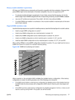
Remove the memory fan and system fan.
4.
Push gently outward on the socket levers, as shown:
Figure 4-30
Opening the DIMM socket locking levers
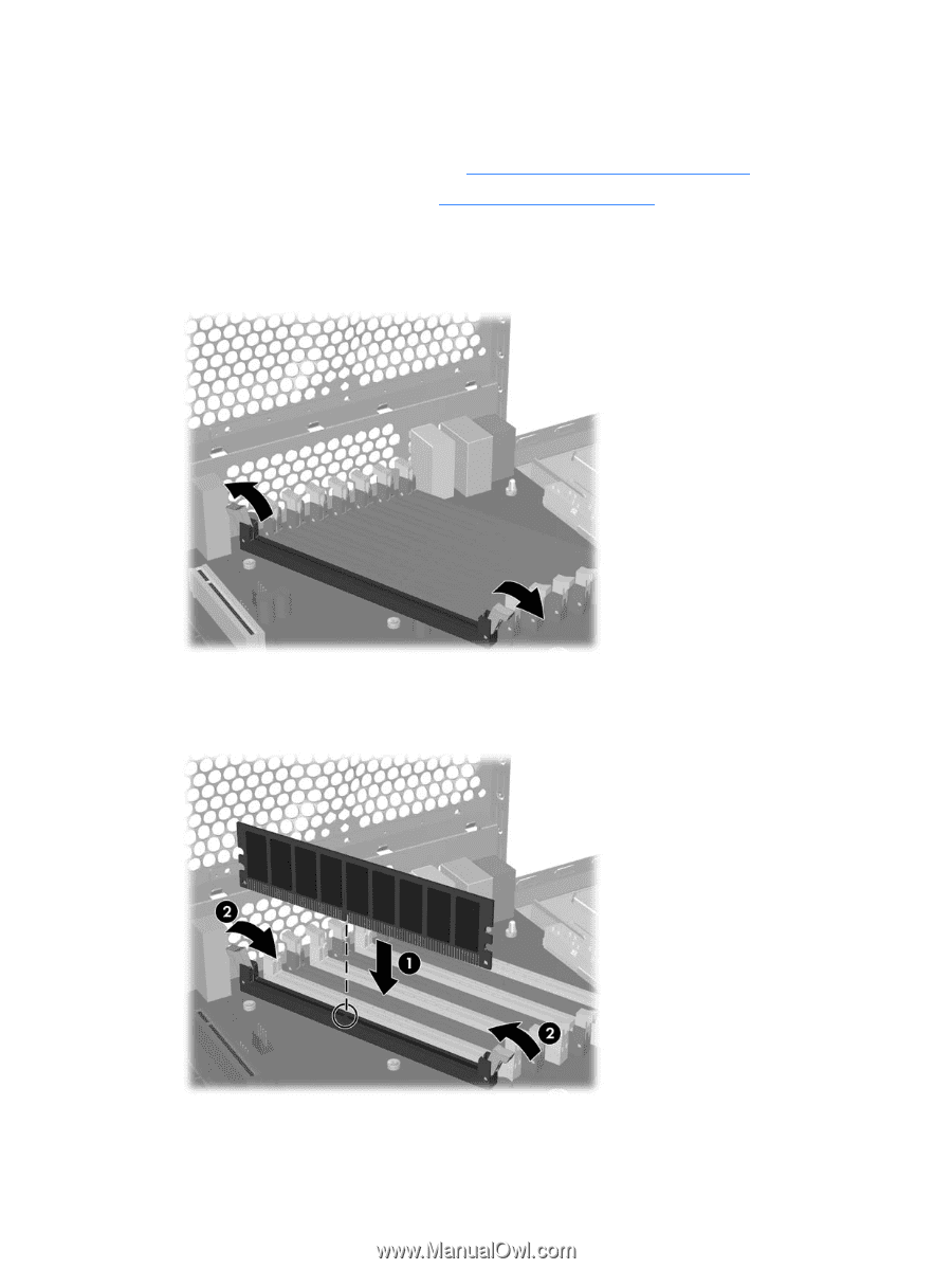
5.
Align the DIMM connector key with the DIMM socket keyway, and then seat the DIMM firmly into
the socket (1), as shown:
Figure 4-31
Installing a memory module
78
Chapter 4
Removal and replacement procedures
ENWW