HP Xw6600 HP xw6600 Workstation Service and Technical Reference Guide - Page 65
Disassembly order
 |
UPC - 883585731121
View all HP Xw6600 manuals
Add to My Manuals
Save this manual to your list of manuals |
Page 65 highlights
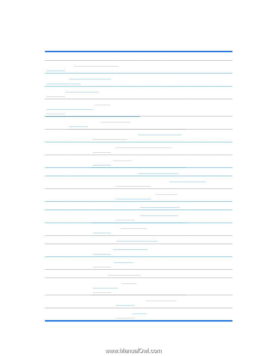
Disassembly order Use the following table to determine the sequence in which to remove major workstation components. Table 4-4 Workstation component disassembly order Predisassembly (Predisassembly procedures on page 52) Security lock (Security lock padlock loop (optional) on page 56 Cable lock (Cable lock (optional) on page 56) Universal chassis clamp lock (Universal chassis clamp lock (optional) on page 57) Side access panel (Side access panel on page 58) Smart Cover Lock solenoid (Smart Cover Lock solenoid (optional) on page 59) Hood Sensor (Hood sensor (Smart cover sensor) on page 61) Front bezel (Front bezel on page 61) Bezel blanks (Bezel blanks on page 62) Front panel I/O device assembly (Front panel I/O device assembly on page 63) Power button assembly (Power button assembly on page 65) Optical drives (Optical drive on page 67 Diskette drive (Diskette drive (optional) on page 69) System speaker (System speaker on page 71) Power supply (Power supply on page 72) System fan (System fan assembly on page 73) Memory fan (Memory fan on page 74) Memory (Memory on page 75) PCI card support (PCI card support bracket on page 80) PCI Express card (PCI Express cards on page 82) PCI card (PCI card on page 84) ENWW Removing and replacing components 55
-
 1
1 -
2
-
3
-
4
-
5
-
6
-
7
-
8
-
9
-
10
-
11
-
12
-
13
-
14
-
15
-
16
-
17
-
18
-
19
-
20
-
21
-
22
-
23
-
24
-
25
-
26
-
27
-
28
-
29
-
30
-
31
-
32
-
33
-
34
-
35
-
36
-
37
-
38
-
39
-
40
-
41
-
42
-
43
-
44
-
45
-
46
-
47
-
48
-
49
-
50
-
51
-
52
-
53
-
54
-
55
-
56
-
57
-
58
-
59
-
 60
60 -
 61
61 -
 62
62 -
 63
63 -
 64
64 -
 65
65 -
 66
66 -
 67
67 -
 68
68 -
 69
69 -
 70
70 -
71
-
72
-
73
-
74
-
75
-
76
-
77
-
78
-
79
-
80
-
81
-
82
-
83
-
84
-
85
-
86
-
87
-
88
-
89
-
90
-
91
-
92
-
93
-
94
-
95
-
96
-
97
-
98
-
99
-
100
-
101
-
102
-
103
-
104
-
105
-
106
-
107
-
108
-
109
-
110
-
111
-
112
-
113
-
114
-
115
-
116
-
117
-
118
-
119
-
120
-
121
-
122
-
123
-
124
-
125
-
126
-
127
-
128
-
129
-
130
-
131
-
132
-
133
-
134
-
135
-
136
-
137
-
138
-
139
-
140
-
141
-
142
-
143
-
144
-
145
-
146
-
147
-
148
-
149
-
150
-
151
-
152
-
153
-
154
-
155
-
156
-
157
-
158
-
159
-
160
-
161
-
162
-
163
-
164
-
165
-
166
-
167
-
168
-
169
-
170
 |
 |