HP Xw6600 HP xw6600 Workstation Service and Technical Reference Guide - Page 64
Removing and replacing components - memory fan
 |
UPC - 883585731121
View all HP Xw6600 manuals
Add to My Manuals
Save this manual to your list of manuals |
Page 64 highlights
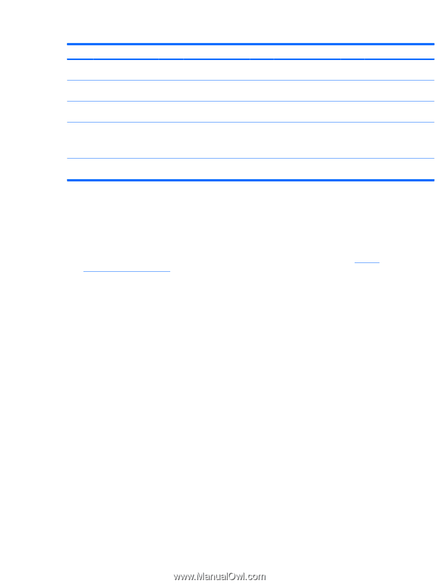
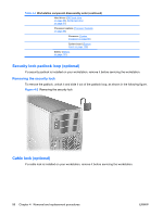
Table 4-3 System board components (continued) Item Component Item Component Item 6 Processor 1 fan connector 16 Clear CMOS button 26 7 Second processor (XU2) 17 Front USB connector 27 8 Memory fan power connector 18 Internal USB connector 28 9 Processor 2 fan connector 19 IDE (PATA) connector 29 10 Diskette drive 20 battery 30 connector * Electrically x4 bandwidth Component PCI 32 slot Item 36 PCI 32 slot 37 PCIe x16 (75W) slot 38 PCIe x8 (4) slot * (openended slot that also allows installation of x16 card ) PCIe x16 (75W +) slot Component Three USB receptacles Two USB and one RJ45 LAN receptacle PS/2 mouse and keyboard jacks Removing and replacing components This section provides procedures to remove and install hardware components on your workstation. 1. Read all safety information and precautions. Before servicing your workstation, review the safety information and precautions in Service considerations on page 48, and the Safety and Regulatory Information for your workstation. 2. Locate and clear a suitable work area. 3. Power down the workstation and disconnect power from the workstation. 4. Gather your tools. 5. Service the workstation. 6. Restore power to the workstation. 54 Chapter 4 Removal and replacement procedures ENWW
-
 1
1 -
2
-
3
-
4
-
5
-
6
-
7
-
8
-
9
-
10
-
11
-
12
-
13
-
14
-
15
-
16
-
17
-
18
-
19
-
20
-
21
-
22
-
23
-
24
-
25
-
26
-
27
-
28
-
29
-
30
-
31
-
32
-
33
-
34
-
35
-
36
-
37
-
38
-
39
-
40
-
41
-
42
-
43
-
44
-
45
-
46
-
47
-
48
-
49
-
50
-
51
-
52
-
53
-
54
-
55
-
56
-
57
-
58
-
 59
59 -
 60
60 -
 61
61 -
 62
62 -
 63
63 -
 64
64 -
 65
65 -
 66
66 -
 67
67 -
 68
68 -
 69
69 -
70
-
71
-
72
-
73
-
74
-
75
-
76
-
77
-
78
-
79
-
80
-
81
-
82
-
83
-
84
-
85
-
86
-
87
-
88
-
89
-
90
-
91
-
92
-
93
-
94
-
95
-
96
-
97
-
98
-
99
-
100
-
101
-
102
-
103
-
104
-
105
-
106
-
107
-
108
-
109
-
110
-
111
-
112
-
113
-
114
-
115
-
116
-
117
-
118
-
119
-
120
-
121
-
122
-
123
-
124
-
125
-
126
-
127
-
128
-
129
-
130
-
131
-
132
-
133
-
134
-
135
-
136
-
137
-
138
-
139
-
140
-
141
-
142
-
143
-
144
-
145
-
146
-
147
-
148
-
149
-
150
-
151
-
152
-
153
-
154
-
155
-
156
-
157
-
158
-
159
-
160
-
161
-
162
-
163
-
164
-
165
-
166
-
167
-
168
-
169
-
170
 |
 |