HP Xw6600 HP xw6600 Workstation Service and Technical Reference Guide - Page 87
Memory module installation requirements, Required DIMM installation order, When powered - beep codes
 |
UPC - 883585731121
View all HP Xw6600 manuals
Add to My Manuals
Save this manual to your list of manuals |
Page 87 highlights
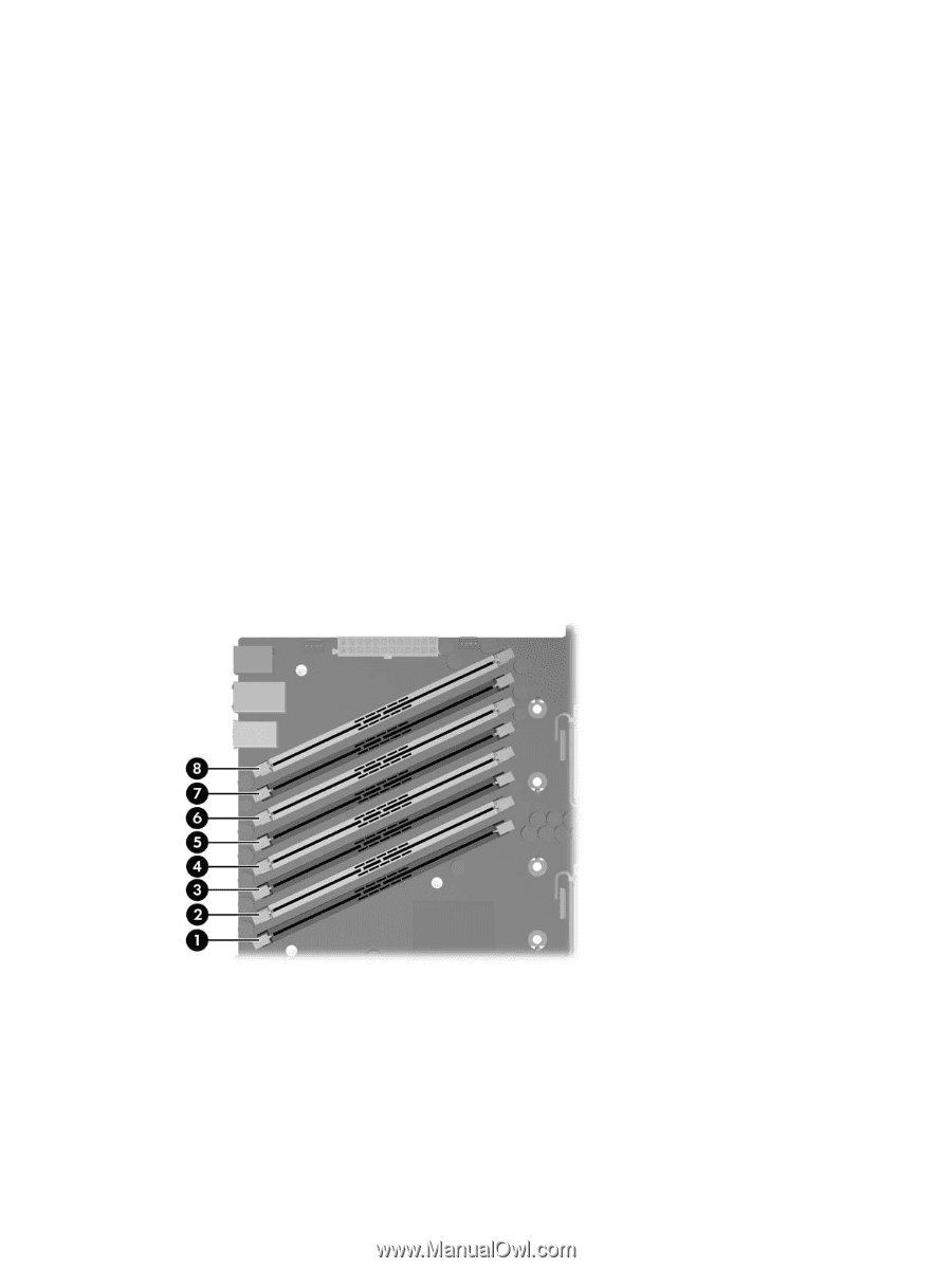
Memory module installation requirements HP ships only DIMMs that are electrically and thermally compatible with this workstation. Because thirdparty DIMMs might not be electrically or thermally compatible, they are not supported by HP. ● To prevent possible damage to equipment or loss of data, ensure that the keyway cut into the bottom edge of each DIMM is aligned with the corresponding socket key as each DIMM is installed. ● Use only HP certified and warranted, PC2-5300F, 667 MHz fully buffered DIMMs. ● If multiple DIMMs are installed in a workstation, they must be installed in matched pairs of the same size in each channel. Required DIMM installation order Use the following sequence as a guide for installing memory (see the following figure for socket location): ● Install a single DIMM configuration in socket 1. ● Install a two-DIMM configuration as a matched pairs in sockets 1/5. ● Install a four-DIMM configuration as two matched pairs in sockets 1/3, and 5/7. ● Install a six-DIMM configuration as three matched pairs in sockets 1/3, 5/7, and 2/4. ● Install an eight-DIMM configuration as four matched pairs in sockets 1/3, 5/7, 2/4, and 6/8. When adding DIMMs to a two-DIMM configuration (installed in sockets 1/5), you might need to move a DIMM from socket 5 to socket 3 to maintain matched pairing. Figure 4-29 DIMM slot numbering and location When powered on, the workstation BIOS validates the installed memory configuration. If the memory configuration is invalid, the BIOS generates one of the following error scenarios: ● If the BIOS cannot obtain a valid memory configuration by disabling some of the installed memory, the BIOS halts the boot process with a diagnostics 2006 code for memory error (five beeps and blinks). ● If the BIOS can find a valid memory configuration by disabling plugged-in memory, it does so and reports a warning during POST. The system can still be booted. ENWW Removing and replacing components 77
-
 1
1 -
2
-
3
-
4
-
5
-
6
-
7
-
8
-
9
-
10
-
11
-
12
-
13
-
14
-
15
-
16
-
17
-
18
-
19
-
20
-
21
-
22
-
23
-
24
-
25
-
26
-
27
-
28
-
29
-
30
-
31
-
32
-
33
-
34
-
35
-
36
-
37
-
38
-
39
-
40
-
41
-
42
-
43
-
44
-
45
-
46
-
47
-
48
-
49
-
50
-
51
-
52
-
53
-
54
-
55
-
56
-
57
-
58
-
59
-
60
-
61
-
62
-
63
-
64
-
65
-
66
-
67
-
68
-
69
-
70
-
71
-
72
-
73
-
74
-
75
-
76
-
77
-
78
-
79
-
80
-
81
-
 82
82 -
 83
83 -
 84
84 -
 85
85 -
 86
86 -
 87
87 -
 88
88 -
 89
89 -
 90
90 -
 91
91 -
 92
92 -
93
-
94
-
95
-
96
-
97
-
98
-
99
-
100
-
101
-
102
-
103
-
104
-
105
-
106
-
107
-
108
-
109
-
110
-
111
-
112
-
113
-
114
-
115
-
116
-
117
-
118
-
119
-
120
-
121
-
122
-
123
-
124
-
125
-
126
-
127
-
128
-
129
-
130
-
131
-
132
-
133
-
134
-
135
-
136
-
137
-
138
-
139
-
140
-
141
-
142
-
143
-
144
-
145
-
146
-
147
-
148
-
149
-
150
-
151
-
152
-
153
-
154
-
155
-
156
-
157
-
158
-
159
-
160
-
161
-
162
-
163
-
164
-
165
-
166
-
167
-
168
-
169
-
170
 |
 |