HP Xw6600 HP xw6600 Workstation Service and Technical Reference Guide - Page 84
Replacing the system fan assembly, Memory fan
 |
UPC - 883585731121
View all HP Xw6600 manuals
Add to My Manuals
Save this manual to your list of manuals |
Page 84 highlights
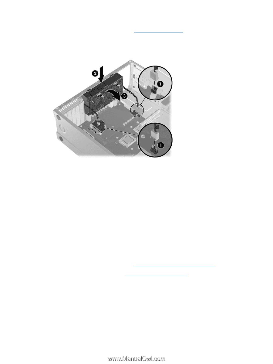
3. Remove the memory fan assembly (see Memory fan on page 74). 4. Disconnect the lower and upper fan plugs from the system board connectors (1), as shown in the following figure. Figure 4-25 Removing the system fan 5. Press in on the ribbed release snap of the system fan housing (2), and then rotate the fan housing down (3). 6. Lift the system fan assembly out of the chassis. Replacing the system fan assembly To replace the system fan assembly, align the four plastic tabs protruding from the bottom back edge of the fan assembly with corresponding mounting holes on the rear of the chassis. Rotate the fan assembly up against the rear chassis panel, and then snap it into place. The fan assembly electrical connectors and their mating system board header connectors are red. To locate the system fan header connectors on the system board, refer to the service label located on the inside of the access panel. Memory fan To remove the memory fan: 1. Disconnect power from the system (see Predisassembly procedures on page 52). 2. Remove the side access panel (see Side access panel on page 58). 74 Chapter 4 Removal and replacement procedures ENWW
-
 1
1 -
2
-
3
-
4
-
5
-
6
-
7
-
8
-
9
-
10
-
11
-
12
-
13
-
14
-
15
-
16
-
17
-
18
-
19
-
20
-
21
-
22
-
23
-
24
-
25
-
26
-
27
-
28
-
29
-
30
-
31
-
32
-
33
-
34
-
35
-
36
-
37
-
38
-
39
-
40
-
41
-
42
-
43
-
44
-
45
-
46
-
47
-
48
-
49
-
50
-
51
-
52
-
53
-
54
-
55
-
56
-
57
-
58
-
59
-
60
-
61
-
62
-
63
-
64
-
65
-
66
-
67
-
68
-
69
-
70
-
71
-
72
-
73
-
74
-
75
-
76
-
77
-
78
-
 79
79 -
 80
80 -
 81
81 -
 82
82 -
 83
83 -
 84
84 -
 85
85 -
 86
86 -
 87
87 -
 88
88 -
 89
89 -
90
-
91
-
92
-
93
-
94
-
95
-
96
-
97
-
98
-
99
-
100
-
101
-
102
-
103
-
104
-
105
-
106
-
107
-
108
-
109
-
110
-
111
-
112
-
113
-
114
-
115
-
116
-
117
-
118
-
119
-
120
-
121
-
122
-
123
-
124
-
125
-
126
-
127
-
128
-
129
-
130
-
131
-
132
-
133
-
134
-
135
-
136
-
137
-
138
-
139
-
140
-
141
-
142
-
143
-
144
-
145
-
146
-
147
-
148
-
149
-
150
-
151
-
152
-
153
-
154
-
155
-
156
-
157
-
158
-
159
-
160
-
161
-
162
-
163
-
164
-
165
-
166
-
167
-
168
-
169
-
170
 |
 |