HP Xw6600 HP xw6600 Workstation Service and Technical Reference Guide - Page 76
Remove the power button assembly mounting screw and rotate the assembly out and away
 |
UPC - 883585731121
View all HP Xw6600 manuals
Add to My Manuals
Save this manual to your list of manuals |
Page 76 highlights
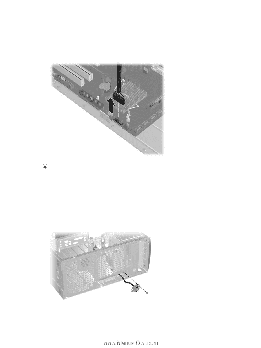
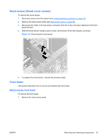
If additional slack is required in the I/O device assembly cables, disconnect the cables from the system board. 5. Disconnect the control panel cable harness from the system board (as shown in the following figure). Figure 4-15 Disconnecting the control panel assembly cable TIP: Remove the optional PCI card guide (if installed) and installed hard drives before attempting to feed the control panel wiring harness out the front of the workstation chassis. 6. If an optional hood sensor is installed, disconnect the white 1x3 hood sensor connector from its mating in-line connector attached to the front panel harness. 7. Disconnect the white speaker cable connector from its mating in-line connector attached to the front panel harness. 8. Remove the power button assembly mounting screw and rotate the assembly out and away from the chassis while feeding the power button assembly cable out through the front of the chassis, as shown in the following figure. Figure 4-16 Removing the power button assembly 66 Chapter 4 Removal and replacement procedures ENWW
-
 1
1 -
2
-
3
-
4
-
5
-
6
-
7
-
8
-
9
-
10
-
11
-
12
-
13
-
14
-
15
-
16
-
17
-
18
-
19
-
20
-
21
-
22
-
23
-
24
-
25
-
26
-
27
-
28
-
29
-
30
-
31
-
32
-
33
-
34
-
35
-
36
-
37
-
38
-
39
-
40
-
41
-
42
-
43
-
44
-
45
-
46
-
47
-
48
-
49
-
50
-
51
-
52
-
53
-
54
-
55
-
56
-
57
-
58
-
59
-
60
-
61
-
62
-
63
-
64
-
65
-
66
-
67
-
68
-
69
-
70
-
 71
71 -
 72
72 -
 73
73 -
 74
74 -
 75
75 -
 76
76 -
 77
77 -
 78
78 -
 79
79 -
 80
80 -
 81
81 -
82
-
83
-
84
-
85
-
86
-
87
-
88
-
89
-
90
-
91
-
92
-
93
-
94
-
95
-
96
-
97
-
98
-
99
-
100
-
101
-
102
-
103
-
104
-
105
-
106
-
107
-
108
-
109
-
110
-
111
-
112
-
113
-
114
-
115
-
116
-
117
-
118
-
119
-
120
-
121
-
122
-
123
-
124
-
125
-
126
-
127
-
128
-
129
-
130
-
131
-
132
-
133
-
134
-
135
-
136
-
137
-
138
-
139
-
140
-
141
-
142
-
143
-
144
-
145
-
146
-
147
-
148
-
149
-
150
-
151
-
152
-
153
-
154
-
155
-
156
-
157
-
158
-
159
-
160
-
161
-
162
-
163
-
164
-
165
-
166
-
167
-
168
-
169
-
170
 |
 |