HP Xw6600 HP xw6600 Workstation Service and Technical Reference Guide - Page 158
SAS drive connector, Segment, Backplane, receptacle, Plug and, cable, receptacles
 |
UPC - 883585731121
View all HP Xw6600 manuals
Add to My Manuals
Save this manual to your list of manuals |
Page 158 highlights
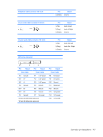
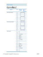
SAS drive connector Segment Primary signal segment Secondary signal segment Power segment Pin Backplane Plug and receptacle cable receptacles S1 SIGNAL GROUND S2 TP+ RP+ S3 TP- RP- S4 SIGNAL GROUND S5 RP- TP- S6 RP+ TP+ S7 SIGNAL GROUND S8 SIGNAL GROUND S9 TS+ S10 TS- RS+ RS- S11 SIGNAL GROUND S12 RS- TS- S13 RS+ TS+ S14 SIGNAL GROUND P1 V33c P2 V33c P3 V33c precharge c P4 GROUND P5 GROUND P6 GROUND P7 V5c precharge c P8 V5c P9 V5c P10 GROUND P11 READY LED d P12 GROUND P13 V12 precharge c P14 V12c P15 V12c 148 Appendix A Appendix A-Connector pins ENWW
-
 1
1 -
2
-
3
-
4
-
5
-
6
-
7
-
8
-
9
-
10
-
11
-
12
-
13
-
14
-
15
-
16
-
17
-
18
-
19
-
20
-
21
-
22
-
23
-
24
-
25
-
26
-
27
-
28
-
29
-
30
-
31
-
32
-
33
-
34
-
35
-
36
-
37
-
38
-
39
-
40
-
41
-
42
-
43
-
44
-
45
-
46
-
47
-
48
-
49
-
50
-
51
-
52
-
53
-
54
-
55
-
56
-
57
-
58
-
59
-
60
-
61
-
62
-
63
-
64
-
65
-
66
-
67
-
68
-
69
-
70
-
71
-
72
-
73
-
74
-
75
-
76
-
77
-
78
-
79
-
80
-
81
-
82
-
83
-
84
-
85
-
86
-
87
-
88
-
89
-
90
-
91
-
92
-
93
-
94
-
95
-
96
-
97
-
98
-
99
-
100
-
101
-
102
-
103
-
104
-
105
-
106
-
107
-
108
-
109
-
110
-
111
-
112
-
113
-
114
-
115
-
116
-
117
-
118
-
119
-
120
-
121
-
122
-
123
-
124
-
125
-
126
-
127
-
128
-
129
-
130
-
131
-
132
-
133
-
134
-
135
-
136
-
137
-
138
-
139
-
140
-
141
-
142
-
143
-
144
-
145
-
146
-
147
-
148
-
149
-
150
-
151
-
152
-
 153
153 -
 154
154 -
 155
155 -
 156
156 -
 157
157 -
 158
158 -
 159
159 -
 160
160 -
 161
161 -
 162
162 -
 163
163 -
164
-
165
-
166
-
167
-
168
-
169
-
170
 |
 |

SAS drive connector
Segment
Pin
Backplane
receptacle
Plug and
cable
receptacles
Primary signal segment
S1
SIGNAL GROUND
S2
TP+
RP+
S3
TP-
RP-
S4
SIGNAL GROUND
S5
RP-
TP-
S6
RP+
TP+
S7
SIGNAL GROUND
Secondary signal segment
S8
SIGNAL GROUND
S9
TS+
RS+
S10
TS-
RS-
S11
SIGNAL GROUND
S12
RS-
TS-
S13
RS+
TS+
S14
SIGNAL GROUND
Power segment
P1
V
33
c
P2
V
33
c
P3
V
33
c
precharge
c
P4
GROUND
P5
GROUND
P6
GROUND
P7
V
5
c
precharge
c
P8
V
5
c
P9
V
5
c
P10
GROUND
P11
READY LED
d
P12
GROUND
P13
V
12
precharge
c
P14
V
12
c
P15
V
12
c
148
Appendix A
Appendix A—Connector pins
ENWW