HP Xw6600 HP xw6600 Workstation Service and Technical Reference Guide - Page 75
Installing the front panel I/O device assembly, Power button assembly
 |
UPC - 883585731121
View all HP Xw6600 manuals
Add to My Manuals
Save this manual to your list of manuals |
Page 75 highlights
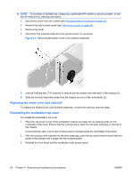
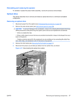
You might need to slide the cables out one at a time. Installing the front panel I/O device assembly To install the front panel I/O device assembly: 1. Thread each front panel I/O device assembly cable through the same holes in the chassis front they were removed from. 2. Using your fingers, manipulate the cables inside the chassis so the front panel I/O device assembly will easily fit in its mounting slot without binding or stress on the cables. 3. Screw the mounting bracket to the chassis. 4. From the front panel I/O device assembly, connect the front audio cable to the system board audio connector (1), and connect the front USB cable to the USB connector (2), as shown in the figure below. Ensure that the front control panel cable to the system board control panel connector is also connected (3). The front panel I/O assembly harness also includes an IEEE 1394 cable. This cable can be connected to an installed IEEE 1394 PCI card, or stowed disconnected under the plastic cable harness clip. Figure 4-14 Attaching the front panel I/O device assembly cables Power button assembly This section describes how to remove the power button assembly. Removing the power button assembly To remove the power button assembly: 1. Disconnect power from the system (see Predisassembly procedures on page 52). 2. Remove the side access panel (see Side access panel on page 58). 3. Remove the front bezel (see Removing the front bezel on page 61). 4. Remove the two I/O device assembly mounting Torx screws and pull the I/O assembly out and away from the chassis approximately two inches (five centimeters). (See Removing the front panel I/O device assembly on page 63.) ENWW Removing and replacing components 65
-
 1
1 -
2
-
3
-
4
-
5
-
6
-
7
-
8
-
9
-
10
-
11
-
12
-
13
-
14
-
15
-
16
-
17
-
18
-
19
-
20
-
21
-
22
-
23
-
24
-
25
-
26
-
27
-
28
-
29
-
30
-
31
-
32
-
33
-
34
-
35
-
36
-
37
-
38
-
39
-
40
-
41
-
42
-
43
-
44
-
45
-
46
-
47
-
48
-
49
-
50
-
51
-
52
-
53
-
54
-
55
-
56
-
57
-
58
-
59
-
60
-
61
-
62
-
63
-
64
-
65
-
66
-
67
-
68
-
69
-
 70
70 -
 71
71 -
 72
72 -
 73
73 -
 74
74 -
 75
75 -
 76
76 -
 77
77 -
 78
78 -
 79
79 -
 80
80 -
81
-
82
-
83
-
84
-
85
-
86
-
87
-
88
-
89
-
90
-
91
-
92
-
93
-
94
-
95
-
96
-
97
-
98
-
99
-
100
-
101
-
102
-
103
-
104
-
105
-
106
-
107
-
108
-
109
-
110
-
111
-
112
-
113
-
114
-
115
-
116
-
117
-
118
-
119
-
120
-
121
-
122
-
123
-
124
-
125
-
126
-
127
-
128
-
129
-
130
-
131
-
132
-
133
-
134
-
135
-
136
-
137
-
138
-
139
-
140
-
141
-
142
-
143
-
144
-
145
-
146
-
147
-
148
-
149
-
150
-
151
-
152
-
153
-
154
-
155
-
156
-
157
-
158
-
159
-
160
-
161
-
162
-
163
-
164
-
165
-
166
-
167
-
168
-
169
-
170
 |
 |