HP Xw6600 HP xw6600 Workstation Service and Technical Reference Guide - Page 111
Battery, Removing the battery, CAUTION, WARNING
 |
UPC - 883585731121
View all HP Xw6600 manuals
Add to My Manuals
Save this manual to your list of manuals |
Page 111 highlights
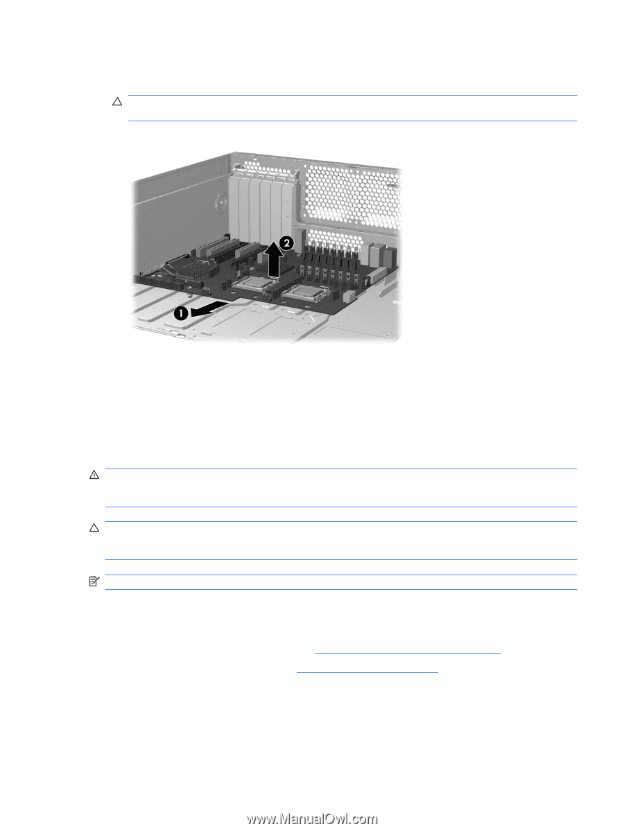
8. As shown in the figure below, slide the system board forward to disengage the metal mounting standoffs from the chassis (1). CAUTION: Do not attempt to remove the system board mounting screws. These are permanently secured and are not removable. Figure 4-61 Removing the system board 9. Lift the system board out of the chassis (2), being careful not to damage the cables and rear panel connectors. Battery This section describes how to remove and install the battery. The battery that comes with the workstation provides power to the real-time clock and has a minimum lifetime of about three years. WARNING! This workstation includes a lithium battery. There is a risk of fire and chemical burn if the battery is handled improperly. Do not disassemble, crush, puncture, short external contacts, dispose in water or fire, or expose it to temperatures higher than 60°C (140°F). CAUTION: Before removing the battery, back up the CMOS settings in case they are lost when the battery is removed. To back up the CMOS settings, select the Save to Diskette option in the Computer Setup (F10) Utility. NOTE: Do not dispose of batteries, battery packs, and accumulators in household waste. Removing the battery To remove the battery: 1. Disconnect power from the system (see Predisassembly procedures on page 52). 2. Remove the side access panel (see Side access panel on page 58). ENWW Removing and replacing components 101
-
 1
1 -
2
-
3
-
4
-
5
-
6
-
7
-
8
-
9
-
10
-
11
-
12
-
13
-
14
-
15
-
16
-
17
-
18
-
19
-
20
-
21
-
22
-
23
-
24
-
25
-
26
-
27
-
28
-
29
-
30
-
31
-
32
-
33
-
34
-
35
-
36
-
37
-
38
-
39
-
40
-
41
-
42
-
43
-
44
-
45
-
46
-
47
-
48
-
49
-
50
-
51
-
52
-
53
-
54
-
55
-
56
-
57
-
58
-
59
-
60
-
61
-
62
-
63
-
64
-
65
-
66
-
67
-
68
-
69
-
70
-
71
-
72
-
73
-
74
-
75
-
76
-
77
-
78
-
79
-
80
-
81
-
82
-
83
-
84
-
85
-
86
-
87
-
88
-
89
-
90
-
91
-
92
-
93
-
94
-
95
-
96
-
97
-
98
-
99
-
100
-
101
-
102
-
103
-
104
-
105
-
 106
106 -
 107
107 -
 108
108 -
 109
109 -
 110
110 -
 111
111 -
 112
112 -
 113
113 -
 114
114 -
 115
115 -
 116
116 -
117
-
118
-
119
-
120
-
121
-
122
-
123
-
124
-
125
-
126
-
127
-
128
-
129
-
130
-
131
-
132
-
133
-
134
-
135
-
136
-
137
-
138
-
139
-
140
-
141
-
142
-
143
-
144
-
145
-
146
-
147
-
148
-
149
-
150
-
151
-
152
-
153
-
154
-
155
-
156
-
157
-
158
-
159
-
160
-
161
-
162
-
163
-
164
-
165
-
166
-
167
-
168
-
169
-
170
 |
 |