HP Xw6600 HP xw6600 Workstation Service and Technical Reference Guide - Page 110
System board, Removing the system board
 |
UPC - 883585731121
View all HP Xw6600 manuals
Add to My Manuals
Save this manual to your list of manuals |
Page 110 highlights
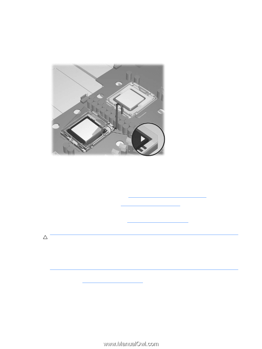
7. As shown in the following figure, align the triangle on the top of the processor with the triangle on the corner of the processor socket, and then install the processor into the socket. Ensure that the underside of the processor is level with the top of the processor socket. Close the socket cover and lightly press down on processor while closing the socket lever. Figure 4-60 Seating the processor 8. Install the processor heatsink on top of the processor. System board Removing the system board 1. Disconnect power from the system (see Predisassembly procedures on page 52). 2. Remove the side access panel (see Side access panel on page 58). 3. Remove all PCIe and PCI cards. 4. Remove both processor heatsinks (see Processor heatsink on page 96). 5. Disconnect all cabling from the system board. CAUTION: Be certain you can differentiate which power cable was disconnected from the PCI Express x16 graphics card, and which power cable was disconnected from the system board. These cables have different pin counts and different colors. The PCI Express power cable has a 6-pin black connector, and the system board power cable has an 8-pin white connector. When power is present, do not connect the PCI Express power cable to the system board. If you do, the system board can be damaged. 6. Record the cable connections before disconnecting them from the system board. For more information, see Power connections on page 73. 7. Verify that the processor heatsinks have been removed. 100 Chapter 4 Removal and replacement procedures ENWW
-
 1
1 -
2
-
3
-
4
-
5
-
6
-
7
-
8
-
9
-
10
-
11
-
12
-
13
-
14
-
15
-
16
-
17
-
18
-
19
-
20
-
21
-
22
-
23
-
24
-
25
-
26
-
27
-
28
-
29
-
30
-
31
-
32
-
33
-
34
-
35
-
36
-
37
-
38
-
39
-
40
-
41
-
42
-
43
-
44
-
45
-
46
-
47
-
48
-
49
-
50
-
51
-
52
-
53
-
54
-
55
-
56
-
57
-
58
-
59
-
60
-
61
-
62
-
63
-
64
-
65
-
66
-
67
-
68
-
69
-
70
-
71
-
72
-
73
-
74
-
75
-
76
-
77
-
78
-
79
-
80
-
81
-
82
-
83
-
84
-
85
-
86
-
87
-
88
-
89
-
90
-
91
-
92
-
93
-
94
-
95
-
96
-
97
-
98
-
99
-
100
-
101
-
102
-
103
-
104
-
 105
105 -
 106
106 -
 107
107 -
 108
108 -
 109
109 -
 110
110 -
 111
111 -
 112
112 -
 113
113 -
 114
114 -
 115
115 -
116
-
117
-
118
-
119
-
120
-
121
-
122
-
123
-
124
-
125
-
126
-
127
-
128
-
129
-
130
-
131
-
132
-
133
-
134
-
135
-
136
-
137
-
138
-
139
-
140
-
141
-
142
-
143
-
144
-
145
-
146
-
147
-
148
-
149
-
150
-
151
-
152
-
153
-
154
-
155
-
156
-
157
-
158
-
159
-
160
-
161
-
162
-
163
-
164
-
165
-
166
-
167
-
168
-
169
-
170
 |
 |