HP Xw6600 HP xw6600 Workstation Service and Technical Reference Guide - Page 74
HP Xw6600 - Workstation - 2 GB RAM Manual
 |
UPC - 883585731121
View all HP Xw6600 manuals
Add to My Manuals
Save this manual to your list of manuals |
Page 74 highlights
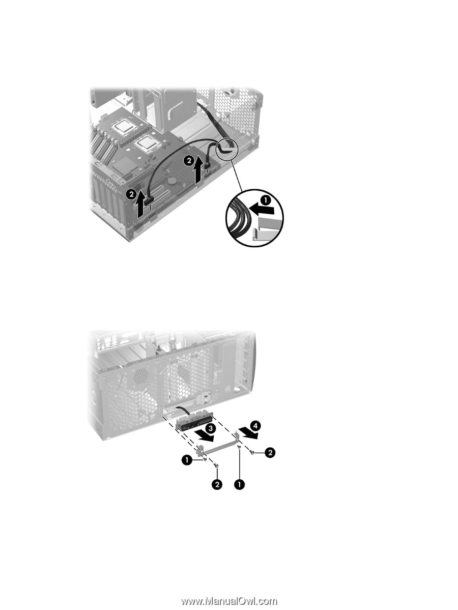
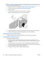
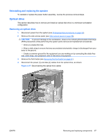
4. Unlatch the plastic snap that secures the cables inside the chassis (1), and then disconnect the front panel I/O device assembly cables from the system board (2), as shown: Figure 4-12 Removing front panel I/O device cables 5. Remove the two smaller Torx screws (1) that hold the front panel I/O device assembly and bracket to the chassis, as shown in the figure below. 6. Although not required, you can remove the mounting bracket from the I/O device assembly by removing the two larger Torx screws (2) and pulling the mounting bracket away separately (4), as shown in the following figure. Figure 4-13 Removing the front panel I/O device assembly 7. Pull the front panel I/O device assembly and bracket out about two inches away from the chassis (3). 8. Guide the front panel cables through the chassis and out through the opening in the front of the workstation chassis. 64 Chapter 4 Removal and replacement procedures ENWW
-
 1
1 -
2
-
3
-
4
-
5
-
6
-
7
-
8
-
9
-
10
-
11
-
12
-
13
-
14
-
15
-
16
-
17
-
18
-
19
-
20
-
21
-
22
-
23
-
24
-
25
-
26
-
27
-
28
-
29
-
30
-
31
-
32
-
33
-
34
-
35
-
36
-
37
-
38
-
39
-
40
-
41
-
42
-
43
-
44
-
45
-
46
-
47
-
48
-
49
-
50
-
51
-
52
-
53
-
54
-
55
-
56
-
57
-
58
-
59
-
60
-
61
-
62
-
63
-
64
-
65
-
66
-
67
-
68
-
 69
69 -
 70
70 -
 71
71 -
 72
72 -
 73
73 -
 74
74 -
 75
75 -
 76
76 -
 77
77 -
 78
78 -
 79
79 -
80
-
81
-
82
-
83
-
84
-
85
-
86
-
87
-
88
-
89
-
90
-
91
-
92
-
93
-
94
-
95
-
96
-
97
-
98
-
99
-
100
-
101
-
102
-
103
-
104
-
105
-
106
-
107
-
108
-
109
-
110
-
111
-
112
-
113
-
114
-
115
-
116
-
117
-
118
-
119
-
120
-
121
-
122
-
123
-
124
-
125
-
126
-
127
-
128
-
129
-
130
-
131
-
132
-
133
-
134
-
135
-
136
-
137
-
138
-
139
-
140
-
141
-
142
-
143
-
144
-
145
-
146
-
147
-
148
-
149
-
150
-
151
-
152
-
153
-
154
-
155
-
156
-
157
-
158
-
159
-
160
-
161
-
162
-
163
-
164
-
165
-
166
-
167
-
168
-
169
-
170
 |
 |