HP LaserJet 9040/9050 Service Manual - Page 13

List of s

Page 13 highlights

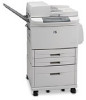
List of figures Figure 1. Sample identification label 6 Figure 2. External view of the printer and accessories 10 Figure 3. Interface connections (HP LaserJet 9040/9050 Series printer) . . . . . 11 Figure 4. Interface connections (HP LaserJet 9000 Series printer 11 Figure 5. Optional accessories 12 Figure 6. Space requirements for the base model 17 Figure 7. Space requirements with a finishing device (3,000-sheet stapler/stacker shown) and tray 4 installed 18 Figure 8. Sample seams 20 Figure 9. Adhesive labels 21 Figure 10. Media trays, bins, and paper handling 25 Figure 11. Control-panel layout 30 Figure 12. Registration page (1 of 2 34 Figure 13. Registration page (2 of 2 35 Figure 14. Turn off the printer and remove the power cords 62 Figure 15. Remove the print cartridge 62 Figure 16. Wipe any residue 63 Figure 17. Replace the print cartridge 63 Figure 18. Lock the print cartridge 63 Figure 19. Close the front cover 64 Figure 20. Sample cleaning page 65 Figure 21. Printer systems 70 Figure 22. Sequence-of-operation block diagram 71 Figure 23. Timing chart block diagram 74 Figure 24. Engine-control-system block diagram 75 Figure 25. DC controller PCA block diagram 76 Figure 26. High-voltage power supply block diagram 78 Figure 27. Power-supply-block diagram 80 Figure 28. Laser/scanner system 83 Figure 29. Image formation 84 Figure 30. Print cartridge 85 Figure 31. Pickup-and-feed system sensors and switches 89 Figure 32. Pickup-and-feed system motors and solenoids 91 Figure 33. Tray 1 block diagram 93 Figure 34. Tray 4 block diagram 95 Figure 35. View of front and right side 100 Figure 36. View of back and left side 100 Figure 37. Right top cover (1 of 2 101 Figure 38. Right top cover (2 of 2 102 Figure 39. Left top cover 103 Figure 40. Front cover (1 of 2 104 Figure 41. Front cover (2 of 2 104 Figure 42. Right door (1 of 2 105 Figure 43. Right door (2 of 2 105 Figure 44. Right lower cover 106 Figure 45. Left door 107 Figure 46. Left back cover 108 Figure 47. Back cover 109 Figure 48. Rail covers 110 xi

  • 1
  • 2
  • 3
  • 4
  • 5
  • 6
  • 7
  • 8
  • 9
  • 10
  • 11
  • 12
  • 13
  • 14
  • 15
  • 16
  • 17
  • 18
  • 19
  • 20
  • 21
  • 22
  • 23
  • 24
  • 25
  • 26
  • 27
  • 28
  • 29
  • 30
  • 31
  • 32
  • 33
  • 34
  • 35
  • 36
  • 37
  • 38
  • 39
  • 40
  • 41
  • 42
  • 43
  • 44
  • 45
  • 46
  • 47
  • 48
  • 49
  • 50
  • 51
  • 52
  • 53
  • 54
  • 55
  • 56
  • 57
  • 58
  • 59
  • 60
  • 61
  • 62
  • 63
  • 64
  • 65
  • 66
  • 67
  • 68
  • 69
  • 70
  • 71
  • 72
  • 73
  • 74
  • 75
  • 76
  • 77
  • 78
  • 79
  • 80
  • 81
  • 82
  • 83
  • 84
  • 85
  • 86
  • 87
  • 88
  • 89
  • 90
  • 91
  • 92
  • 93
  • 94
  • 95
  • 96
  • 97
  • 98
  • 99
  • 100
  • 101
  • 102
  • 103
  • 104
  • 105
  • 106
  • 107
  • 108
  • 109
  • 110
  • 111
  • 112
  • 113
  • 114
  • 115
  • 116
  • 117
  • 118
  • 119
  • 120
  • 121
  • 122
  • 123
  • 124
  • 125
  • 126
  • 127
  • 128
  • 129
  • 130
  • 131
  • 132
  • 133
  • 134
  • 135
  • 136
  • 137
  • 138
  • 139
  • 140
  • 141
  • 142
  • 143
  • 144
  • 145
  • 146
  • 147
  • 148
  • 149
  • 150
  • 151
  • 152
  • 153
  • 154
  • 155
  • 156
  • 157
  • 158
  • 159
  • 160
  • 161
  • 162
  • 163
  • 164
  • 165
  • 166
  • 167
  • 168
  • 169
  • 170
  • 171
  • 172
  • 173
  • 174
  • 175
  • 176
  • 177
  • 178
  • 179
  • 180
  • 181
  • 182
  • 183
  • 184
  • 185
  • 186
  • 187
  • 188
  • 189
  • 190
  • 191
  • 192
  • 193
  • 194
  • 195
  • 196
  • 197
  • 198
  • 199
  • 200
  • 201
  • 202
  • 203
  • 204
  • 205
  • 206
  • 207
  • 208
  • 209
  • 210
  • 211
  • 212
  • 213
  • 214
  • 215
  • 216
  • 217
  • 218
  • 219
  • 220
  • 221
  • 222
  • 223
  • 224
  • 225
  • 226
  • 227
  • 228
  • 229
  • 230
  • 231
  • 232
  • 233
  • 234
  • 235
  • 236
  • 237
  • 238
  • 239
  • 240
  • 241
  • 242
  • 243
  • 244
  • 245
  • 246
  • 247
  • 248
  • 249
  • 250
  • 251
  • 252
  • 253
  • 254
  • 255
  • 256
  • 257
  • 258
  • 259
  • 260
  • 261
  • 262
  • 263
  • 264
  • 265
  • 266
  • 267
  • 268
  • 269
  • 270
  • 271
  • 272
  • 273
  • 274
  • 275
  • 276
  • 277
  • 278
  • 279
  • 280
  • 281
  • 282
  • 283
  • 284
  • 285
  • 286
  • 287
  • 288
  • 289
  • 290
  • 291
  • 292
  • 293
  • 294
  • 295
  • 296
  • 297
  • 298
  • 299
  • 300
  • 301
  • 302
  • 303
  • 304
  • 305
  • 306
  • 307
  • 308
  • 309
  • 310
  • 311
  • 312
  • 313
  • 314
  • 315
  • 316
  • 317
  • 318
  • 319
  • 320
  • 321
  • 322
  • 323
  • 324
  • 325
  • 326
  • 327
  • 328
  • 329
  • 330
  • 331
  • 332

xi
List of figures
Figure 1. Sample identification label
. . . . . . . . . . . . . . . . . . . . . . . . . . . . . . . . . . 6
Figure 2. External view of the printer and accessories . . . . . . . . . . . . . . . . . . . . 10
Figure 3. Interface connections (HP LaserJet 9040/9050 Series printer)
. . . . . 11
Figure 4. Interface connections (HP LaserJet 9000 Series printer) . . . . . . . . . . 11
Figure 5. Optional accessories
. . . . . . . . . . . . . . . . . . . . . . . . . . . . . . . . . . . . . 12
Figure 6. Space requirements for the base model . . . . . . . . . . . . . . . . . . . . . . . 17
Figure 7. Space requirements with a finishing device
(3,000-sheet stapler/stacker shown) and tray 4 installed . . . . . . . . . . . . . . . 18
Figure 8. Sample seams
. . . . . . . . . . . . . . . . . . . . . . . . . . . . . . . . . . . . . . . . . . 20
Figure 9. Adhesive labels . . . . . . . . . . . . . . . . . . . . . . . . . . . . . . . . . . . . . . . . . . 21
Figure 10. Media trays, bins, and paper handling
. . . . . . . . . . . . . . . . . . . . . . . 25
Figure 11. Control-panel layout
. . . . . . . . . . . . . . . . . . . . . . . . . . . . . . . . . . . . . 30
Figure 12. Registration page (1 of 2)
. . . . . . . . . . . . . . . . . . . . . . . . . . . . . . . . . 34
Figure 13. Registration page (2 of 2)
. . . . . . . . . . . . . . . . . . . . . . . . . . . . . . . . . 35
Figure 14. Turn off the printer and remove the power cords
. . . . . . . . . . . . . . . 62
Figure 15. Remove the print cartridge
. . . . . . . . . . . . . . . . . . . . . . . . . . . . . . . . 62
Figure 16. Wipe any residue
. . . . . . . . . . . . . . . . . . . . . . . . . . . . . . . . . . . . . . . 63
Figure 17. Replace the print cartridge
. . . . . . . . . . . . . . . . . . . . . . . . . . . . . . . . 63
Figure 18. Lock the print cartridge
. . . . . . . . . . . . . . . . . . . . . . . . . . . . . . . . . . . 63
Figure 19. Close the front cover . . . . . . . . . . . . . . . . . . . . . . . . . . . . . . . . . . . . . 64
Figure 20. Sample cleaning page . . . . . . . . . . . . . . . . . . . . . . . . . . . . . . . . . . . . 65
Figure 21. Printer systems . . . . . . . . . . . . . . . . . . . . . . . . . . . . . . . . . . . . . . . . . 70
Figure 22. Sequence-of-operation block diagram
. . . . . . . . . . . . . . . . . . . . . . . 71
Figure 23. Timing chart block diagram . . . . . . . . . . . . . . . . . . . . . . . . . . . . . . . . 74
Figure 24. Engine-control-system block diagram . . . . . . . . . . . . . . . . . . . . . . . . 75
Figure 25. DC controller PCA block diagram . . . . . . . . . . . . . . . . . . . . . . . . . . . 76
Figure 26. High-voltage power supply block diagram
. . . . . . . . . . . . . . . . . . . . 78
Figure 27. Power-supply-block diagram . . . . . . . . . . . . . . . . . . . . . . . . . . . . . . . 80
Figure 28. Laser/scanner system . . . . . . . . . . . . . . . . . . . . . . . . . . . . . . . . . . . . 83
Figure 29. Image formation
. . . . . . . . . . . . . . . . . . . . . . . . . . . . . . . . . . . . . . . . 84
Figure 30. Print cartridge
. . . . . . . . . . . . . . . . . . . . . . . . . . . . . . . . . . . . . . . . . . 85
Figure 31. Pickup-and-feed system sensors and switches
. . . . . . . . . . . . . . . . 89
Figure 32. Pickup-and-feed system motors and solenoids
. . . . . . . . . . . . . . . . 91
Figure 33. Tray 1 block diagram . . . . . . . . . . . . . . . . . . . . . . . . . . . . . . . . . . . . . 93
Figure 34. Tray 4 block diagram . . . . . . . . . . . . . . . . . . . . . . . . . . . . . . . . . . . . . 95
Figure 35. View of front and right side
. . . . . . . . . . . . . . . . . . . . . . . . . . . . . . . 100
Figure 36. View of back and left side . . . . . . . . . . . . . . . . . . . . . . . . . . . . . . . . 100
Figure 37. Right top cover (1 of 2)
. . . . . . . . . . . . . . . . . . . . . . . . . . . . . . . . . . 101
Figure 38. Right top cover (2 of 2)
. . . . . . . . . . . . . . . . . . . . . . . . . . . . . . . . . . 102
Figure 39. Left top cover
. . . . . . . . . . . . . . . . . . . . . . . . . . . . . . . . . . . . . . . . . 103
Figure 40. Front cover (1 of 2)
. . . . . . . . . . . . . . . . . . . . . . . . . . . . . . . . . . . . . 104
Figure 41. Front cover (2 of 2)
. . . . . . . . . . . . . . . . . . . . . . . . . . . . . . . . . . . . . 104
Figure 42. Right door (1 of 2) . . . . . . . . . . . . . . . . . . . . . . . . . . . . . . . . . . . . . . 105
Figure 43. Right door (2 of 2) . . . . . . . . . . . . . . . . . . . . . . . . . . . . . . . . . . . . . . 105
Figure 44. Right lower cover
. . . . . . . . . . . . . . . . . . . . . . . . . . . . . . . . . . . . . . 106
Figure 45. Left door
. . . . . . . . . . . . . . . . . . . . . . . . . . . . . . . . . . . . . . . . . . . . . 107
Figure 46. Left back cover
. . . . . . . . . . . . . . . . . . . . . . . . . . . . . . . . . . . . . . . . 108
Figure 47. Back cover
. . . . . . . . . . . . . . . . . . . . . . . . . . . . . . . . . . . . . . . . . . . 109
Figure 48. Rail covers
. . . . . . . . . . . . . . . . . . . . . . . . . . . . . . . . . . . . . . . . . . . 110