Netgear GS724Tv4 Software Administration Manual - Page 112
IGMP Snooping Table, Fast Leave Admin Mode
 |
View all Netgear GS724Tv4 manuals
Add to My Manuals
Save this manual to your list of manuals |
Page 112 highlights
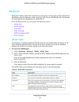
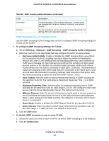
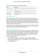
GS716Tv3, GS724Tv4, and GS748Tv5 Smart Switches 3. Configure the IGMP snooping values for the selected ports or LAGs: • Admin Mode. Select the interface mode for the selected interface for IGMP snooping for the switch from the menu. The default is Disable. • Host Timeout. Specify the amount of time you want the switch to wait for a report for a particular group on a particular interface before it deletes that interface from the group. Enter a value between 2 and 3600 seconds. The default is 260 seconds. • Max Response Time. Specify the amount of time you want the switch to wait after sending a query on an interface because it did not receive a report for a particular group on that interface. Enter a value greater or equal to 1 and less than the Host Timeout, in seconds. The default is 10 seconds. • MRouter Timeout. Specify the amount of time you want the switch to wait to receive a query on an interface before removing it from the list of interfaces with multicast routers attached. Enter a value between 0 and 3600 seconds. The default is 0 seconds. A value of zero indicates an infinite time-out; no expiration. • Fast Leave Admin Mode. Select the Fast Leave mode for a particular interface from the menu. The default is Disable. 4. Click the Apply button. IGMP Snooping Table Use the IGMP Snooping Table screen to view all of the entries in the Multicast Forwarding Database that were created for IGMP snooping. To view the entries in the IGMP snooping table: 1. Select Switching > Multicast > IGMP Snooping > IGMP Snooping Table. 2. Next to Search By MAC Address, specify the MAC Address whose MFDB table entry you want to view. Enter six two-digit hexadecimal numbers separated by colons, for example 00:01:23:43:45:67. The following table describes the information in the IGMP snooping table. Table 33. IGMP snooping table information Field MAC Address VLAN ID Type Description A multicast MAC address for which the switch has forwarding and/or filtering information. The format is 6 two-digit hexadecimal numbers that are separated by colons, for example, 01:00:5e:45:67:89. A VLAN ID for which the switch has forwarding and filtering information. This displays the type of the entry. Static entries are those that are configured by the end user. Dynamic entries are added to the table as a result of a learning process or protocol. Configuring Switching 112
-
 1
1 -
2
-
3
-
4
-
5
-
6
-
7
-
8
-
9
-
10
-
11
-
12
-
13
-
14
-
15
-
16
-
17
-
18
-
19
-
20
-
21
-
22
-
23
-
24
-
25
-
26
-
27
-
28
-
29
-
30
-
31
-
32
-
33
-
34
-
35
-
36
-
37
-
38
-
39
-
40
-
41
-
42
-
43
-
44
-
45
-
46
-
47
-
48
-
49
-
50
-
51
-
52
-
53
-
54
-
55
-
56
-
57
-
58
-
59
-
60
-
61
-
62
-
63
-
64
-
65
-
66
-
67
-
68
-
69
-
70
-
71
-
72
-
73
-
74
-
75
-
76
-
77
-
78
-
79
-
80
-
81
-
82
-
83
-
84
-
85
-
86
-
87
-
88
-
89
-
90
-
91
-
92
-
93
-
94
-
95
-
96
-
97
-
98
-
99
-
100
-
101
-
102
-
103
-
104
-
105
-
106
-
 107
107 -
 108
108 -
 109
109 -
 110
110 -
 111
111 -
 112
112 -
 113
113 -
 114
114 -
 115
115 -
 116
116 -
 117
117 -
118
-
119
-
120
-
121
-
122
-
123
-
124
-
125
-
126
-
127
-
128
-
129
-
130
-
131
-
132
-
133
-
134
-
135
-
136
-
137
-
138
-
139
-
140
-
141
-
142
-
143
-
144
-
145
-
146
-
147
-
148
-
149
-
150
-
151
-
152
-
153
-
154
-
155
-
156
-
157
-
158
-
159
-
160
-
161
-
162
-
163
-
164
-
165
-
166
-
167
-
168
-
169
-
170
-
171
-
172
-
173
-
174
-
175
-
176
-
177
-
178
-
179
-
180
-
181
-
182
-
183
-
184
-
185
-
186
-
187
-
188
-
189
-
190
-
191
-
192
-
193
-
194
-
195
-
196
-
197
-
198
-
199
-
200
-
201
-
202
-
203
-
204
-
205
-
206
-
207
-
208
-
209
-
210
-
211
-
212
-
213
-
214
-
215
-
216
-
217
-
218
-
219
-
220
-
221
-
222
-
223
-
224
-
225
-
226
-
227
-
228
-
229
-
230
-
231
-
232
-
233
-
234
-
235
-
236
-
237
-
238
-
239
-
240
-
241
-
242
-
243
-
244
-
245
-
246
-
247
-
248
-
249
-
250
-
251
-
252
-
253
-
254
-
255
-
256
-
257
-
258
-
259
-
260
-
261
-
262
-
263
-
264
-
265
-
266
-
267
-
268
-
269
-
270
-
271
-
272
-
273
-
274
-
275
-
276
-
277
-
278
-
279
-
280
-
281
-
282
-
283
-
284
-
285
-
286
-
287
-
288
-
289
-
290
 |
 |