Netgear GS724Tv4 Software Administration Manual - Page 264
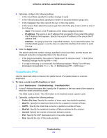
A VLAN with VLAN ID 20.
 |
View all Netgear GS724Tv4 manuals
Add to My Manuals
Save this manual to your list of manuals |
Page 264 highlights
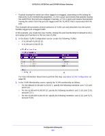
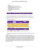
GS716Tv3, GS724Tv4, and GS748Tv5 Smart Switches • Packets leaving the switch are either tagged or untagged, depending on the setting for that port's VLAN membership properties. A U for a given port means that packets leaving the switch from that port are untagged. Inversely, a T for a given port means that packets leaving the switch from that port are tagged with the VLAN ID that is associated with the port. This example demonstrates several scenarios of VLAN use and describes how the switch handles tagged and untagged traffic. In this example, you create two new VLANs, change the port membership for default VLAN 1, and assign port members to the two new VLANs: 1. In the Basic VLAN Configuration screen create the following VLANs: • A VLAN with VLAN ID 10. • A VLAN with VLAN ID 20. For more information about how to perform this step, see Basic VLAN Configuration on page 88. 2. In the VLAN Membership screen, specify the VLAN membership as follows: • For the default VLAN with VLAN ID 1, specify the following members: port 7 (U) and port 8 (U). • For the VLAN with VLAN ID 10, specify the following members: port 1 (U), port 2 (U), and port 3 (T). • For the VLAN with VLAN ID 20, specify the following members: port 4 (U), port 5 (T), and port 6 (U). Configuration Examples 264
-
 1
1 -
2
-
3
-
4
-
5
-
6
-
7
-
8
-
9
-
10
-
11
-
12
-
13
-
14
-
15
-
16
-
17
-
18
-
19
-
20
-
21
-
22
-
23
-
24
-
25
-
26
-
27
-
28
-
29
-
30
-
31
-
32
-
33
-
34
-
35
-
36
-
37
-
38
-
39
-
40
-
41
-
42
-
43
-
44
-
45
-
46
-
47
-
48
-
49
-
50
-
51
-
52
-
53
-
54
-
55
-
56
-
57
-
58
-
59
-
60
-
61
-
62
-
63
-
64
-
65
-
66
-
67
-
68
-
69
-
70
-
71
-
72
-
73
-
74
-
75
-
76
-
77
-
78
-
79
-
80
-
81
-
82
-
83
-
84
-
85
-
86
-
87
-
88
-
89
-
90
-
91
-
92
-
93
-
94
-
95
-
96
-
97
-
98
-
99
-
100
-
101
-
102
-
103
-
104
-
105
-
106
-
107
-
108
-
109
-
110
-
111
-
112
-
113
-
114
-
115
-
116
-
117
-
118
-
119
-
120
-
121
-
122
-
123
-
124
-
125
-
126
-
127
-
128
-
129
-
130
-
131
-
132
-
133
-
134
-
135
-
136
-
137
-
138
-
139
-
140
-
141
-
142
-
143
-
144
-
145
-
146
-
147
-
148
-
149
-
150
-
151
-
152
-
153
-
154
-
155
-
156
-
157
-
158
-
159
-
160
-
161
-
162
-
163
-
164
-
165
-
166
-
167
-
168
-
169
-
170
-
171
-
172
-
173
-
174
-
175
-
176
-
177
-
178
-
179
-
180
-
181
-
182
-
183
-
184
-
185
-
186
-
187
-
188
-
189
-
190
-
191
-
192
-
193
-
194
-
195
-
196
-
197
-
198
-
199
-
200
-
201
-
202
-
203
-
204
-
205
-
206
-
207
-
208
-
209
-
210
-
211
-
212
-
213
-
214
-
215
-
216
-
217
-
218
-
219
-
220
-
221
-
222
-
223
-
224
-
225
-
226
-
227
-
228
-
229
-
230
-
231
-
232
-
233
-
234
-
235
-
236
-
237
-
238
-
239
-
240
-
241
-
242
-
243
-
244
-
245
-
246
-
247
-
248
-
249
-
250
-
251
-
252
-
253
-
254
-
255
-
256
-
257
-
258
-
 259
259 -
 260
260 -
 261
261 -
 262
262 -
 263
263 -
 264
264 -
 265
265 -
 266
266 -
 267
267 -
 268
268 -
 269
269 -
270
-
271
-
272
-
273
-
274
-
275
-
276
-
277
-
278
-
279
-
280
-
281
-
282
-
283
-
284
-
285
-
286
-
287
-
288
-
289
-
290
 |
 |