Netgear GS724Tv4 Software Administration Manual - Page 273
X Configuration Example
 |
View all Netgear GS724Tv4 manuals
Add to My Manuals
Save this manual to your list of manuals |
Page 273 highlights
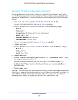
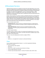
GS716Tv3, GS724Tv4, and GS748Tv5 Smart Switches 9. From the Service Configuration screen, select the check box next to interfaces g7 and g8 to attach the policy to these interfaces, For more information about this step, see Service Configuration on page 176. 10. Click the Apply button. All UDP packet flows destined to the 192.12.2.0 network with an IP source address from the 192.12.1.0 network that have a Layer 4 Source port of 4567 and Destination port of 4568 from this switch on ports 7 and 8 are assigned to hardware queue 3. On this network, traffic from streaming applications uses UDP port 4567 as the source and 4568 as the destination. This real-time traffic is time sensitive, so it is assigned to a high-priority hardware queue. By default, data traffic uses hardware queue 0, which is designated as a best-effort queue. Also the confirmed action on this flow is to send the packets with a committed rate of 1,000,000 Kbps and burst size of 128 KB. Packets that violate the committed rate and burst size are dropped. 802.1X Configuration Example Local Area Networks (LANs) are often deployed in environments that permit unauthorized devices to be physically attached to the LAN infrastructure, or permit unauthorized users to attempt to access the LAN through equipment already attached. In such environments, it can be desirable to restrict access to the services offered by the LAN to those users and devices that are permitted to use those services. Port-based network access control makes use of the physical characteristics of LAN infrastructures in order to provide a means of authenticating and authorizing devices attached to a LAN port that has point-to-point connection characteristics and of preventing access to that port in cases in which the authentication and authorization process fails. In this context, a port is a single point of attachment to the LAN, such as ports of MAC bridges and associations between stations or access points in IEEE 802.11 Wireless LANs. The IEEE 802.11 standard describes an architectural framework within which authentication and consequent actions take place. It also establishes the requirements for a protocol between the authenticator (the system that passes an authentication request to the authentication server) and the supplicant (the system that requests authentication), as well as between the authenticator and the authentication server. The switch supports a guest VLAN, which allows unauthenticated users to have limited access to the network resources. Note: You can use QoS features to provide rate limiting on the guest VLAN to limit the network resources the guest VLAN provides. Configuration Examples 273
-
 1
1 -
2
-
3
-
4
-
5
-
6
-
7
-
8
-
9
-
10
-
11
-
12
-
13
-
14
-
15
-
16
-
17
-
18
-
19
-
20
-
21
-
22
-
23
-
24
-
25
-
26
-
27
-
28
-
29
-
30
-
31
-
32
-
33
-
34
-
35
-
36
-
37
-
38
-
39
-
40
-
41
-
42
-
43
-
44
-
45
-
46
-
47
-
48
-
49
-
50
-
51
-
52
-
53
-
54
-
55
-
56
-
57
-
58
-
59
-
60
-
61
-
62
-
63
-
64
-
65
-
66
-
67
-
68
-
69
-
70
-
71
-
72
-
73
-
74
-
75
-
76
-
77
-
78
-
79
-
80
-
81
-
82
-
83
-
84
-
85
-
86
-
87
-
88
-
89
-
90
-
91
-
92
-
93
-
94
-
95
-
96
-
97
-
98
-
99
-
100
-
101
-
102
-
103
-
104
-
105
-
106
-
107
-
108
-
109
-
110
-
111
-
112
-
113
-
114
-
115
-
116
-
117
-
118
-
119
-
120
-
121
-
122
-
123
-
124
-
125
-
126
-
127
-
128
-
129
-
130
-
131
-
132
-
133
-
134
-
135
-
136
-
137
-
138
-
139
-
140
-
141
-
142
-
143
-
144
-
145
-
146
-
147
-
148
-
149
-
150
-
151
-
152
-
153
-
154
-
155
-
156
-
157
-
158
-
159
-
160
-
161
-
162
-
163
-
164
-
165
-
166
-
167
-
168
-
169
-
170
-
171
-
172
-
173
-
174
-
175
-
176
-
177
-
178
-
179
-
180
-
181
-
182
-
183
-
184
-
185
-
186
-
187
-
188
-
189
-
190
-
191
-
192
-
193
-
194
-
195
-
196
-
197
-
198
-
199
-
200
-
201
-
202
-
203
-
204
-
205
-
206
-
207
-
208
-
209
-
210
-
211
-
212
-
213
-
214
-
215
-
216
-
217
-
218
-
219
-
220
-
221
-
222
-
223
-
224
-
225
-
226
-
227
-
228
-
229
-
230
-
231
-
232
-
233
-
234
-
235
-
236
-
237
-
238
-
239
-
240
-
241
-
242
-
243
-
244
-
245
-
246
-
247
-
248
-
249
-
250
-
251
-
252
-
253
-
254
-
255
-
256
-
257
-
258
-
259
-
260
-
261
-
262
-
263
-
264
-
265
-
266
-
267
-
 268
268 -
 269
269 -
 270
270 -
 271
271 -
 272
272 -
 273
273 -
 274
274 -
 275
275 -
 276
276 -
 277
277 -
 278
278 -
279
-
280
-
281
-
282
-
283
-
284
-
285
-
286
-
287
-
288
-
289
-
290
 |
 |
