Netgear GS724Tv4 Software Administration Manual - Page 259
TraceRoute IPv4, Probes Per Hop
 |
View all Netgear GS724Tv4 manuals
Add to My Manuals
Save this manual to your list of manuals |
Page 259 highlights
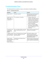
GS716Tv3, GS724Tv4, and GS748Tv5 Smart Switches 4. Optionally, configure the following settings: • In the Count field, specify the number of pings to send. • In the Interval (secs) field, specify the number of seconds between pings sent. • In the Datagram Size field, specify the size of the ping packet. • In the Source field, select the source type from which the ping is sent, which is one of the following: - None. The source is the IP address of the default outgoing interface. - IP address. The source is an IP address that you specify. If you select this option, the IP Address field appears. Specify the source IP address of the ping in the IP address field. - Interface. The ping is sent from a specified interface. If you select this option, the Interface field appears. Use the menu to select the interface from which to send the ping. 5. Click the Apply button. The switch sends the number of pings specified in the Count field, and the results are displayed below the configurable data in the Result area: • If the ping is successful, the output is "Send count=3, Receive count = n from (IPv6 Address).Average round trip time = n ms". • If a reply to the ping is not received, the following displays: "Reply From IP/Host: Destination Unreachable. Tx = x, Rx = 0 Min/Max/Avg RTT = 0/0/0 msec." TraceRoute IPv4 Use the traceroute utility to discover the paths that an IPv4 packet takes to a remote destination. To trace a route to an IPv4 address or host: 1. Select Maintenance > Troubleshooting > TraceRoute IPv4. 2. In the IP Address/Hostname field, specify the IP address or the host name of the station to which the switch should find a path. The initial value is blank. This information is not retained across a power cycle. 3. Optionally, configure the following settings: • Probes Per Hop. Specify the number of times each hop should be probed. • MaxTTL. Specify the maximum time-to-live for a packet in number of hops. • InitTTL. Specify the initial time-to-live for a packet in number of hops. • MaxFail. Specify the maximum number of failures allowed in the session. • Interval. Specify the number of seconds between probes. • Port. Specify the UDP destination port in the probe packets. • Size. Specify the size of the probe packets. Troubleshooting 259
-
 1
1 -
2
-
3
-
4
-
5
-
6
-
7
-
8
-
9
-
10
-
11
-
12
-
13
-
14
-
15
-
16
-
17
-
18
-
19
-
20
-
21
-
22
-
23
-
24
-
25
-
26
-
27
-
28
-
29
-
30
-
31
-
32
-
33
-
34
-
35
-
36
-
37
-
38
-
39
-
40
-
41
-
42
-
43
-
44
-
45
-
46
-
47
-
48
-
49
-
50
-
51
-
52
-
53
-
54
-
55
-
56
-
57
-
58
-
59
-
60
-
61
-
62
-
63
-
64
-
65
-
66
-
67
-
68
-
69
-
70
-
71
-
72
-
73
-
74
-
75
-
76
-
77
-
78
-
79
-
80
-
81
-
82
-
83
-
84
-
85
-
86
-
87
-
88
-
89
-
90
-
91
-
92
-
93
-
94
-
95
-
96
-
97
-
98
-
99
-
100
-
101
-
102
-
103
-
104
-
105
-
106
-
107
-
108
-
109
-
110
-
111
-
112
-
113
-
114
-
115
-
116
-
117
-
118
-
119
-
120
-
121
-
122
-
123
-
124
-
125
-
126
-
127
-
128
-
129
-
130
-
131
-
132
-
133
-
134
-
135
-
136
-
137
-
138
-
139
-
140
-
141
-
142
-
143
-
144
-
145
-
146
-
147
-
148
-
149
-
150
-
151
-
152
-
153
-
154
-
155
-
156
-
157
-
158
-
159
-
160
-
161
-
162
-
163
-
164
-
165
-
166
-
167
-
168
-
169
-
170
-
171
-
172
-
173
-
174
-
175
-
176
-
177
-
178
-
179
-
180
-
181
-
182
-
183
-
184
-
185
-
186
-
187
-
188
-
189
-
190
-
191
-
192
-
193
-
194
-
195
-
196
-
197
-
198
-
199
-
200
-
201
-
202
-
203
-
204
-
205
-
206
-
207
-
208
-
209
-
210
-
211
-
212
-
213
-
214
-
215
-
216
-
217
-
218
-
219
-
220
-
221
-
222
-
223
-
224
-
225
-
226
-
227
-
228
-
229
-
230
-
231
-
232
-
233
-
234
-
235
-
236
-
237
-
238
-
239
-
240
-
241
-
242
-
243
-
244
-
245
-
246
-
247
-
248
-
249
-
250
-
251
-
252
-
253
-
 254
254 -
 255
255 -
 256
256 -
 257
257 -
 258
258 -
 259
259 -
 260
260 -
 261
261 -
 262
262 -
 263
263 -
 264
264 -
265
-
266
-
267
-
268
-
269
-
270
-
271
-
272
-
273
-
274
-
275
-
276
-
277
-
278
-
279
-
280
-
281
-
282
-
283
-
284
-
285
-
286
-
287
-
288
-
289
-
290
 |
 |