Netgear GS724Tv4 Software Administration Manual - Page 275
Apply, Server Address, Secret Con d, Secret, Active, From the 802.1X Configuration screen
 |
View all Netgear GS724Tv4 manuals
Add to My Manuals
Save this manual to your list of manuals |
Page 275 highlights
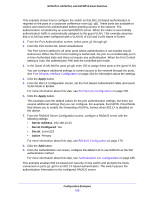
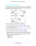
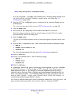
GS716Tv3, GS724Tv4, and GS748Tv5 Smart Switches This example shows how to configure the switch so that 802.1X-based authentication is required on the ports in a corporate conference room (g1-g8). These ports are available to visitors and need to be authenticated before granting access to the network. The authentication is handled by an external RADIUS server. When the visitor is successfully authenticated, traffic is automatically assigned to the guest VLAN. This example assumes that a VLAN has been configured with a VLAN ID of 150 and VLAN Name of Guest. 1. From the Port Authentication screen, select ports g1 through g8. 2. From the Port Control list, select Unauthorized. The Port Control setting for all other ports where authentication is not needed should Authorized. When the Port Control setting is Authorized, the port is unconditionally put in a force-Authorized state and does not require any authentication. When the Port Control setting is Auto, the authenticator PAE sets the controlled port mode. 3. In the Guest VLAN field for ports g1-g8, enter 150 to assign these ports to the guest VLAN. You can configure additional settings to control access to the network through the ports. See Port Security Interface Configuration on page 203 for information about the settings. 4. Click the Apply button. 5. From the 802.1X Configuration screen, set the Port Based Authentication State and Guest VLAN Mode to Enable. For more information about this step, see Port Security Configuration on page 203. 6. Click the Apply button. This example uses the default values for the port authentication settings, but there are several additional settings that you can configure. For example, the EAPOL Flood Mode field allows you to enable the forwarding of EAPoL frames when 802.1X is disabled on the device. 7. From the RADIUS Server Configuration screen, configure a RADIUS server with the following settings: • Server Address. 192.168.10.23 • Secret Configured. Yes • Secret. secret123 • Active. Primary For more information about this step, see RADIUS Configuration on page 179. 8. Click the Add button. 9. From the Authentication List screen, configure the default List to use RADIUS as the first authentication method. For more information about this step, see Authentication List Configuration on page 185. This example enables 802.1X-based port security on the switch and prompts the hosts connected on ports g1-g8 for an 802.1X-based authentication. The switch passes the authentication information to the configured RADIUS server. Configuration Examples 275
-
 1
1 -
2
-
3
-
4
-
5
-
6
-
7
-
8
-
9
-
10
-
11
-
12
-
13
-
14
-
15
-
16
-
17
-
18
-
19
-
20
-
21
-
22
-
23
-
24
-
25
-
26
-
27
-
28
-
29
-
30
-
31
-
32
-
33
-
34
-
35
-
36
-
37
-
38
-
39
-
40
-
41
-
42
-
43
-
44
-
45
-
46
-
47
-
48
-
49
-
50
-
51
-
52
-
53
-
54
-
55
-
56
-
57
-
58
-
59
-
60
-
61
-
62
-
63
-
64
-
65
-
66
-
67
-
68
-
69
-
70
-
71
-
72
-
73
-
74
-
75
-
76
-
77
-
78
-
79
-
80
-
81
-
82
-
83
-
84
-
85
-
86
-
87
-
88
-
89
-
90
-
91
-
92
-
93
-
94
-
95
-
96
-
97
-
98
-
99
-
100
-
101
-
102
-
103
-
104
-
105
-
106
-
107
-
108
-
109
-
110
-
111
-
112
-
113
-
114
-
115
-
116
-
117
-
118
-
119
-
120
-
121
-
122
-
123
-
124
-
125
-
126
-
127
-
128
-
129
-
130
-
131
-
132
-
133
-
134
-
135
-
136
-
137
-
138
-
139
-
140
-
141
-
142
-
143
-
144
-
145
-
146
-
147
-
148
-
149
-
150
-
151
-
152
-
153
-
154
-
155
-
156
-
157
-
158
-
159
-
160
-
161
-
162
-
163
-
164
-
165
-
166
-
167
-
168
-
169
-
170
-
171
-
172
-
173
-
174
-
175
-
176
-
177
-
178
-
179
-
180
-
181
-
182
-
183
-
184
-
185
-
186
-
187
-
188
-
189
-
190
-
191
-
192
-
193
-
194
-
195
-
196
-
197
-
198
-
199
-
200
-
201
-
202
-
203
-
204
-
205
-
206
-
207
-
208
-
209
-
210
-
211
-
212
-
213
-
214
-
215
-
216
-
217
-
218
-
219
-
220
-
221
-
222
-
223
-
224
-
225
-
226
-
227
-
228
-
229
-
230
-
231
-
232
-
233
-
234
-
235
-
236
-
237
-
238
-
239
-
240
-
241
-
242
-
243
-
244
-
245
-
246
-
247
-
248
-
249
-
250
-
251
-
252
-
253
-
254
-
255
-
256
-
257
-
258
-
259
-
260
-
261
-
262
-
263
-
264
-
265
-
266
-
267
-
268
-
269
-
 270
270 -
 271
271 -
 272
272 -
 273
273 -
 274
274 -
 275
275 -
 276
276 -
 277
277 -
 278
278 -
 279
279 -
 280
280 -
281
-
282
-
283
-
284
-
285
-
286
-
287
-
288
-
289
-
290
 |
 |