Netgear GS724Tv4 Software Administration Manual - Page 265
VLAN Membership Configuration, Port VLAN ID Configuration, Port g4: PVID 20
 |
View all Netgear GS724Tv4 manuals
Add to My Manuals
Save this manual to your list of manuals |
Page 265 highlights
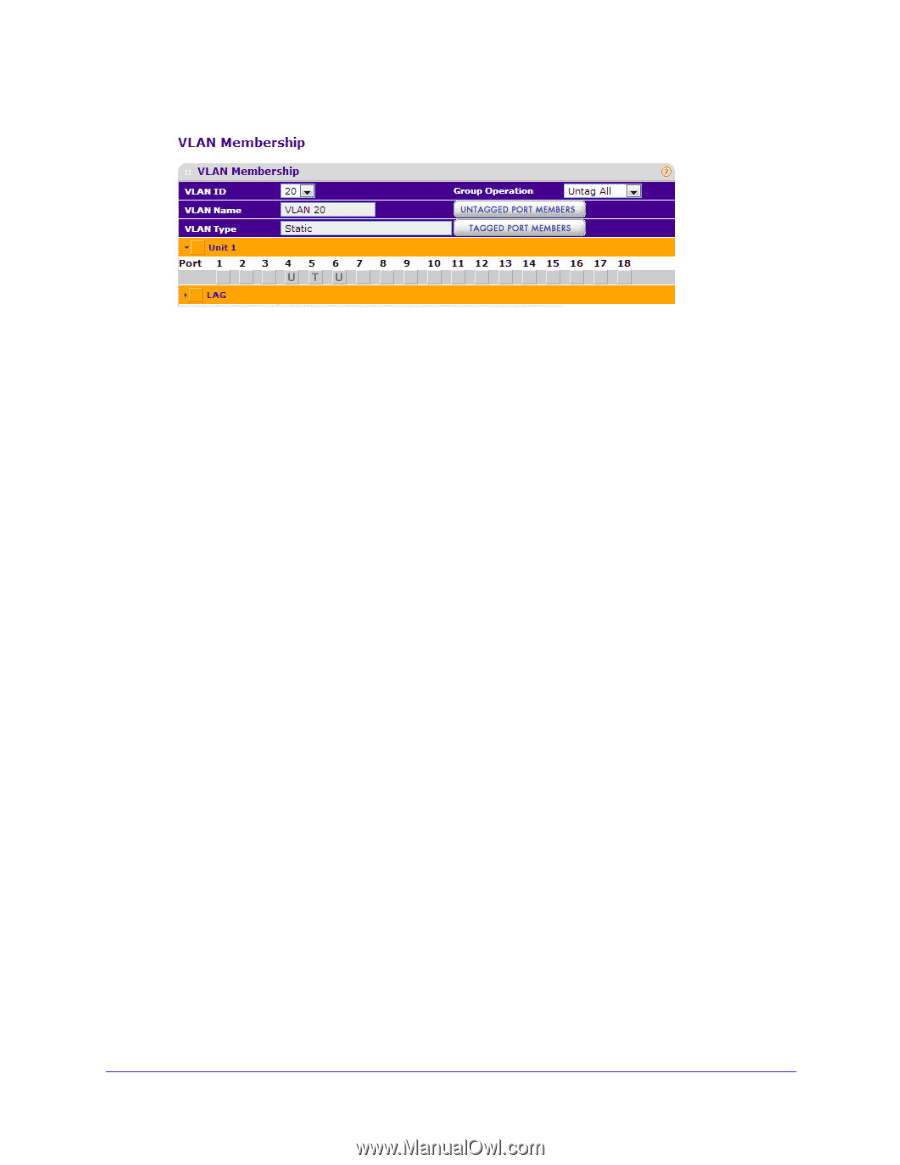
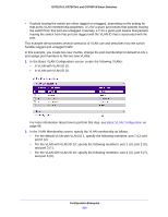
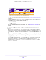
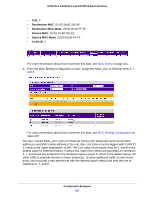
GS716Tv3, GS724Tv4, and GS748Tv5 Smart Switches For more information about how to perform this step, see VLAN Membership Configuration on page 89. 3. In the Port PVID Configuration screen, specify the PVID for ports g1 and g4 so that packets entering these ports are tagged with the port VLAN ID: • Port g1: PVID 10 • Port g4: PVID 20 For more information about how to perform this step, see Port VLAN ID Configuration on page 91. With the VLAN configuration that you set up, the following situations produce results as described: • If an untagged packet enters port 1, the switch tags it with VLAN ID 10. The packet has access to port 2 and port 3. The outgoing packet is stripped of its tag to leave port 2 as an untagged packet. For port 3, the outgoing packet leaves as a tagged packet with VLAN ID 10. • If a tagged packet with VLAN ID 10 enters port 3, the packet has access to port 1 and port 2. If the packet leaves port 1 or port 2, it is stripped of its tag to leave the switch as an untagged packet. • If an untagged packet enters port 4, the switch tags it with VLAN ID 20. The packet has access to port 5 and port 6. The outgoing packet is stripped of its tag to become an untagged packet as it leaves port 6. For port 5, the outgoing packet leaves as a tagged packet with VLAN ID 20. Configuration Examples 265
-
 1
1 -
2
-
3
-
4
-
5
-
6
-
7
-
8
-
9
-
10
-
11
-
12
-
13
-
14
-
15
-
16
-
17
-
18
-
19
-
20
-
21
-
22
-
23
-
24
-
25
-
26
-
27
-
28
-
29
-
30
-
31
-
32
-
33
-
34
-
35
-
36
-
37
-
38
-
39
-
40
-
41
-
42
-
43
-
44
-
45
-
46
-
47
-
48
-
49
-
50
-
51
-
52
-
53
-
54
-
55
-
56
-
57
-
58
-
59
-
60
-
61
-
62
-
63
-
64
-
65
-
66
-
67
-
68
-
69
-
70
-
71
-
72
-
73
-
74
-
75
-
76
-
77
-
78
-
79
-
80
-
81
-
82
-
83
-
84
-
85
-
86
-
87
-
88
-
89
-
90
-
91
-
92
-
93
-
94
-
95
-
96
-
97
-
98
-
99
-
100
-
101
-
102
-
103
-
104
-
105
-
106
-
107
-
108
-
109
-
110
-
111
-
112
-
113
-
114
-
115
-
116
-
117
-
118
-
119
-
120
-
121
-
122
-
123
-
124
-
125
-
126
-
127
-
128
-
129
-
130
-
131
-
132
-
133
-
134
-
135
-
136
-
137
-
138
-
139
-
140
-
141
-
142
-
143
-
144
-
145
-
146
-
147
-
148
-
149
-
150
-
151
-
152
-
153
-
154
-
155
-
156
-
157
-
158
-
159
-
160
-
161
-
162
-
163
-
164
-
165
-
166
-
167
-
168
-
169
-
170
-
171
-
172
-
173
-
174
-
175
-
176
-
177
-
178
-
179
-
180
-
181
-
182
-
183
-
184
-
185
-
186
-
187
-
188
-
189
-
190
-
191
-
192
-
193
-
194
-
195
-
196
-
197
-
198
-
199
-
200
-
201
-
202
-
203
-
204
-
205
-
206
-
207
-
208
-
209
-
210
-
211
-
212
-
213
-
214
-
215
-
216
-
217
-
218
-
219
-
220
-
221
-
222
-
223
-
224
-
225
-
226
-
227
-
228
-
229
-
230
-
231
-
232
-
233
-
234
-
235
-
236
-
237
-
238
-
239
-
240
-
241
-
242
-
243
-
244
-
245
-
246
-
247
-
248
-
249
-
250
-
251
-
252
-
253
-
254
-
255
-
256
-
257
-
258
-
259
-
 260
260 -
 261
261 -
 262
262 -
 263
263 -
 264
264 -
 265
265 -
 266
266 -
 267
267 -
 268
268 -
 269
269 -
 270
270 -
271
-
272
-
273
-
274
-
275
-
276
-
277
-
278
-
279
-
280
-
281
-
282
-
283
-
284
-
285
-
286
-
287
-
288
-
289
-
290
 |
 |