Netgear GS724Tv4 Software Administration Manual - Page 37
IP Configuration, Dynamic IP Address DHCP
 |
View all Netgear GS724Tv4 manuals
Add to My Manuals
Save this manual to your list of manuals |
Page 37 highlights
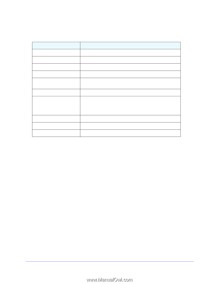
GS716Tv3, GS724Tv4, and GS748Tv5 Smart Switches The following table describes the status information the System Information screen displays. Table 4. System Information screen status fields Field Product Name Serial Number System Object ID Date & Time System Up Time Base MAC Address Fan Status Model Name Boot Version Software Version Description The product name that describes the switch. The serial number of the switch. The base object ID for the switch's enterprise MIB. The current date and time. The number of days, hours, and minutes since the last system restart. The universally assigned network address. The screen shows the status of the fans. These fans remove the heat generated by the power, CPU and other chipsets, make chipsets work normally. Fan status has three possible values: OK, Failure, Not Present. The model name of the switch. The boot code version of the switch. The software version of the switch. IP Configuration Use the IP Configuration screen to configure network information for the management interface, which is the logical interface used for in-band connectivity with the switch through any of the switch's front-panel ports. The configuration parameters associated with the switch's network interface do not affect the configuration of the front panel ports through which traffic is switched or routed. To configure the network information for the management interface: 1. Select System > Management > IP Configuration. 2. Select the appropriate radio button to determine how to configure the network information for the switch management interface: • Dynamic IP Address (DHCP). Specifies that the switch must obtain the IP address through a DHCP server. • Dynamic IP Address (BOOTP). Specifies that the switch must obtain the IP address through a BootP server. • Static IP Address. Specifies that the IP address, subnet mask, and default gateway must be manually configured. Enter this information in the fields below this radio button. Configure System Information 37
-
 1
1 -
2
-
3
-
4
-
5
-
6
-
7
-
8
-
9
-
10
-
11
-
12
-
13
-
14
-
15
-
16
-
17
-
18
-
19
-
20
-
21
-
22
-
23
-
24
-
25
-
26
-
27
-
28
-
29
-
30
-
31
-
 32
32 -
 33
33 -
 34
34 -
 35
35 -
 36
36 -
 37
37 -
 38
38 -
 39
39 -
 40
40 -
 41
41 -
 42
42 -
43
-
44
-
45
-
46
-
47
-
48
-
49
-
50
-
51
-
52
-
53
-
54
-
55
-
56
-
57
-
58
-
59
-
60
-
61
-
62
-
63
-
64
-
65
-
66
-
67
-
68
-
69
-
70
-
71
-
72
-
73
-
74
-
75
-
76
-
77
-
78
-
79
-
80
-
81
-
82
-
83
-
84
-
85
-
86
-
87
-
88
-
89
-
90
-
91
-
92
-
93
-
94
-
95
-
96
-
97
-
98
-
99
-
100
-
101
-
102
-
103
-
104
-
105
-
106
-
107
-
108
-
109
-
110
-
111
-
112
-
113
-
114
-
115
-
116
-
117
-
118
-
119
-
120
-
121
-
122
-
123
-
124
-
125
-
126
-
127
-
128
-
129
-
130
-
131
-
132
-
133
-
134
-
135
-
136
-
137
-
138
-
139
-
140
-
141
-
142
-
143
-
144
-
145
-
146
-
147
-
148
-
149
-
150
-
151
-
152
-
153
-
154
-
155
-
156
-
157
-
158
-
159
-
160
-
161
-
162
-
163
-
164
-
165
-
166
-
167
-
168
-
169
-
170
-
171
-
172
-
173
-
174
-
175
-
176
-
177
-
178
-
179
-
180
-
181
-
182
-
183
-
184
-
185
-
186
-
187
-
188
-
189
-
190
-
191
-
192
-
193
-
194
-
195
-
196
-
197
-
198
-
199
-
200
-
201
-
202
-
203
-
204
-
205
-
206
-
207
-
208
-
209
-
210
-
211
-
212
-
213
-
214
-
215
-
216
-
217
-
218
-
219
-
220
-
221
-
222
-
223
-
224
-
225
-
226
-
227
-
228
-
229
-
230
-
231
-
232
-
233
-
234
-
235
-
236
-
237
-
238
-
239
-
240
-
241
-
242
-
243
-
244
-
245
-
246
-
247
-
248
-
249
-
250
-
251
-
252
-
253
-
254
-
255
-
256
-
257
-
258
-
259
-
260
-
261
-
262
-
263
-
264
-
265
-
266
-
267
-
268
-
269
-
270
-
271
-
272
-
273
-
274
-
275
-
276
-
277
-
278
-
279
-
280
-
281
-
282
-
283
-
284
-
285
-
286
-
287
-
288
-
289
-
290
 |
 |