Netgear GS724Tv4 Software Administration Manual - Page 239
Logs, Memory Logs, FLASH Log, Server Log, Trap Logs, Event Logs
 |
View all Netgear GS724Tv4 manuals
Add to My Manuals
Save this manual to your list of manuals |
Page 239 highlights
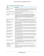
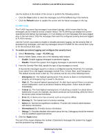
GS716Tv3, GS724Tv4, and GS748Tv5 Smart Switches The following table describes the cable information displayed on the screen. Table 74. Cable information Field Port Cable Status Cable Length Failure Location Description Specifies the port that has the connected cable. The cable status. • Normal. The cable is working correctly. • Open. The cable is disconnected or there is a faulty connector. • Short. There is an electrical short in the cable. • Cable Test Failed. The cable status could not be determined. The cable can in fact be working. • Unknown. The test has not been performed. The estimated length of the cable in meters. The length is displayed as a range between the shortest estimated length and the longest estimated length. Unknown is displayed if the cable length could not be determined. The Cable Length is displayed only if the cable status is Normal. The estimated distance in meters from the end of the cable to the failure location. The failure location is displayed only if the cable status is Open or Short. Logs The switch can generate messages in response to events, faults, or errors occurring on the platform as well as changes in configuration or other occurrences. These messages are stored locally and can be forwarded to one or more centralized points of collection for monitoring purposes or long term archival storage. Local and remote configuration of the logging capability includes filtering of messages logged or forwarded based on severity and generating component. The Logs menu contains links to the features described in the following sections. • Memory Logs • FLASH Log • Server Log • Trap Logs • Event Logs Monitoring the System 239
-
 1
1 -
2
-
3
-
4
-
5
-
6
-
7
-
8
-
9
-
10
-
11
-
12
-
13
-
14
-
15
-
16
-
17
-
18
-
19
-
20
-
21
-
22
-
23
-
24
-
25
-
26
-
27
-
28
-
29
-
30
-
31
-
32
-
33
-
34
-
35
-
36
-
37
-
38
-
39
-
40
-
41
-
42
-
43
-
44
-
45
-
46
-
47
-
48
-
49
-
50
-
51
-
52
-
53
-
54
-
55
-
56
-
57
-
58
-
59
-
60
-
61
-
62
-
63
-
64
-
65
-
66
-
67
-
68
-
69
-
70
-
71
-
72
-
73
-
74
-
75
-
76
-
77
-
78
-
79
-
80
-
81
-
82
-
83
-
84
-
85
-
86
-
87
-
88
-
89
-
90
-
91
-
92
-
93
-
94
-
95
-
96
-
97
-
98
-
99
-
100
-
101
-
102
-
103
-
104
-
105
-
106
-
107
-
108
-
109
-
110
-
111
-
112
-
113
-
114
-
115
-
116
-
117
-
118
-
119
-
120
-
121
-
122
-
123
-
124
-
125
-
126
-
127
-
128
-
129
-
130
-
131
-
132
-
133
-
134
-
135
-
136
-
137
-
138
-
139
-
140
-
141
-
142
-
143
-
144
-
145
-
146
-
147
-
148
-
149
-
150
-
151
-
152
-
153
-
154
-
155
-
156
-
157
-
158
-
159
-
160
-
161
-
162
-
163
-
164
-
165
-
166
-
167
-
168
-
169
-
170
-
171
-
172
-
173
-
174
-
175
-
176
-
177
-
178
-
179
-
180
-
181
-
182
-
183
-
184
-
185
-
186
-
187
-
188
-
189
-
190
-
191
-
192
-
193
-
194
-
195
-
196
-
197
-
198
-
199
-
200
-
201
-
202
-
203
-
204
-
205
-
206
-
207
-
208
-
209
-
210
-
211
-
212
-
213
-
214
-
215
-
216
-
217
-
218
-
219
-
220
-
221
-
222
-
223
-
224
-
225
-
226
-
227
-
228
-
229
-
230
-
231
-
232
-
233
-
 234
234 -
 235
235 -
 236
236 -
 237
237 -
 238
238 -
 239
239 -
 240
240 -
 241
241 -
 242
242 -
 243
243 -
 244
244 -
245
-
246
-
247
-
248
-
249
-
250
-
251
-
252
-
253
-
254
-
255
-
256
-
257
-
258
-
259
-
260
-
261
-
262
-
263
-
264
-
265
-
266
-
267
-
268
-
269
-
270
-
271
-
272
-
273
-
274
-
275
-
276
-
277
-
278
-
279
-
280
-
281
-
282
-
283
-
284
-
285
-
286
-
287
-
288
-
289
-
290
 |
 |