Netgear GS724Tv4 Software Administration Manual - Page 280
VLAN Routing Interface Configuration Example
 |
View all Netgear GS724Tv4 manuals
Add to My Manuals
Save this manual to your list of manuals |
Page 280 highlights
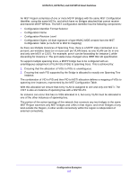
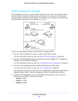
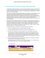
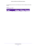
GS716Tv3, GS724Tv4, and GS748Tv5 Smart Switches VLAN Routing Interface Configuration Example VLANs divide broadcast domains in a LAN environment. Whenever hosts in one VLAN need to communicate with hosts in another VLAN, the traffic must be routed between them. This is known as inter-VLAN routing. On the switch, it is accomplished by creating Layer 3 interfaces (switch virtual interfaces (SVI)). When a port is enabled for bridging (default) rather than routing, all normal bridge processing is performed for an inbound packet, which is then associated with a VLAN. Its MAC destination address (MAC DA) and VLAN ID are used to search the MAC address table. If routing is enabled for the VLAN, and the MAC DA of an inbound unicast packet is that of the internal bridge-router interface, the packet is routed. An inbound multicast packet is forwarded to all ports in the VLAN, plus the internal bridge-router interface, if it was received on a routed VLAN. Since a port can be configured to belong to more than one VLAN, VLAN routing might be enabled for all of the VLANs on the port, or for a subset. VLAN Routing can be used to allow more than one physical port to reside on the same subnet. It could also be used when a VLAN spans multiple physical networks, or when additional segmentation or security is required. A port can be either a VLAN port or a router port, but not both. However, a VLAN port can be part of a VLAN that is itself a router port. Complete these steps to configure a switch to perform interVLAN routing. 1. Use the IP Configuration screen to enable routing on the switch. For more information about this step, see IP Configuration on page 148). 2. Determine the IP addresses you want to assign to the VLAN interface on the switch. For the switch to be able to route between the VLANs, the VLAN interfaces must be configured with an IP address. When the switch receives a packet destined for another subnet/VLAN, the switch looks at the routing table to determine where to forward the packet. The packet is then passed to the VLAN interface of the destination. It is then sent to the port where the end device is attached. 3. Use the VLAN Routing Wizard screen to create a routing VLAN, configure the IP address and subnet mask, and to add the member ports. In the following figure, VLAN 300 is created with IP address 10.1.2.1 and subnet mask 255.255.255.0, with ports 9, 10, and 11 as untagged members. Configuration Examples 280
-
 1
1 -
2
-
3
-
4
-
5
-
6
-
7
-
8
-
9
-
10
-
11
-
12
-
13
-
14
-
15
-
16
-
17
-
18
-
19
-
20
-
21
-
22
-
23
-
24
-
25
-
26
-
27
-
28
-
29
-
30
-
31
-
32
-
33
-
34
-
35
-
36
-
37
-
38
-
39
-
40
-
41
-
42
-
43
-
44
-
45
-
46
-
47
-
48
-
49
-
50
-
51
-
52
-
53
-
54
-
55
-
56
-
57
-
58
-
59
-
60
-
61
-
62
-
63
-
64
-
65
-
66
-
67
-
68
-
69
-
70
-
71
-
72
-
73
-
74
-
75
-
76
-
77
-
78
-
79
-
80
-
81
-
82
-
83
-
84
-
85
-
86
-
87
-
88
-
89
-
90
-
91
-
92
-
93
-
94
-
95
-
96
-
97
-
98
-
99
-
100
-
101
-
102
-
103
-
104
-
105
-
106
-
107
-
108
-
109
-
110
-
111
-
112
-
113
-
114
-
115
-
116
-
117
-
118
-
119
-
120
-
121
-
122
-
123
-
124
-
125
-
126
-
127
-
128
-
129
-
130
-
131
-
132
-
133
-
134
-
135
-
136
-
137
-
138
-
139
-
140
-
141
-
142
-
143
-
144
-
145
-
146
-
147
-
148
-
149
-
150
-
151
-
152
-
153
-
154
-
155
-
156
-
157
-
158
-
159
-
160
-
161
-
162
-
163
-
164
-
165
-
166
-
167
-
168
-
169
-
170
-
171
-
172
-
173
-
174
-
175
-
176
-
177
-
178
-
179
-
180
-
181
-
182
-
183
-
184
-
185
-
186
-
187
-
188
-
189
-
190
-
191
-
192
-
193
-
194
-
195
-
196
-
197
-
198
-
199
-
200
-
201
-
202
-
203
-
204
-
205
-
206
-
207
-
208
-
209
-
210
-
211
-
212
-
213
-
214
-
215
-
216
-
217
-
218
-
219
-
220
-
221
-
222
-
223
-
224
-
225
-
226
-
227
-
228
-
229
-
230
-
231
-
232
-
233
-
234
-
235
-
236
-
237
-
238
-
239
-
240
-
241
-
242
-
243
-
244
-
245
-
246
-
247
-
248
-
249
-
250
-
251
-
252
-
253
-
254
-
255
-
256
-
257
-
258
-
259
-
260
-
261
-
262
-
263
-
264
-
265
-
266
-
267
-
268
-
269
-
270
-
271
-
272
-
273
-
274
-
 275
275 -
 276
276 -
 277
277 -
 278
278 -
 279
279 -
 280
280 -
 281
281 -
 282
282 -
 283
283 -
 284
284 -
 285
285 -
286
-
287
-
288
-
289
-
290
 |
 |